
To configure SNMP traps using the FlowVision GUI, navigate to Configuration > SNMP Traps.
The SNMP Traps configuration page lists connected devices and their respective configured SNMP Traps. You can select individual devices and define SNMP traps.
The following image shows the SNMP Trap page with the switches and configured SNMP Traps:
To create an SNMP Trap,
Start by clicking on the button
Select the switch to configure the SNMP Trap
Configure the SNMP trap Server-ID, Version, Destination IP, Destination Port and community string
To delete the existing SNMP Trap, click the icon.
Click on
SNMP Trap is now configured


To view and configure rule templates from the FlowVision GUI, click Configuration > Rule Templates.
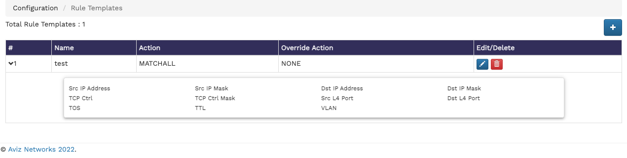
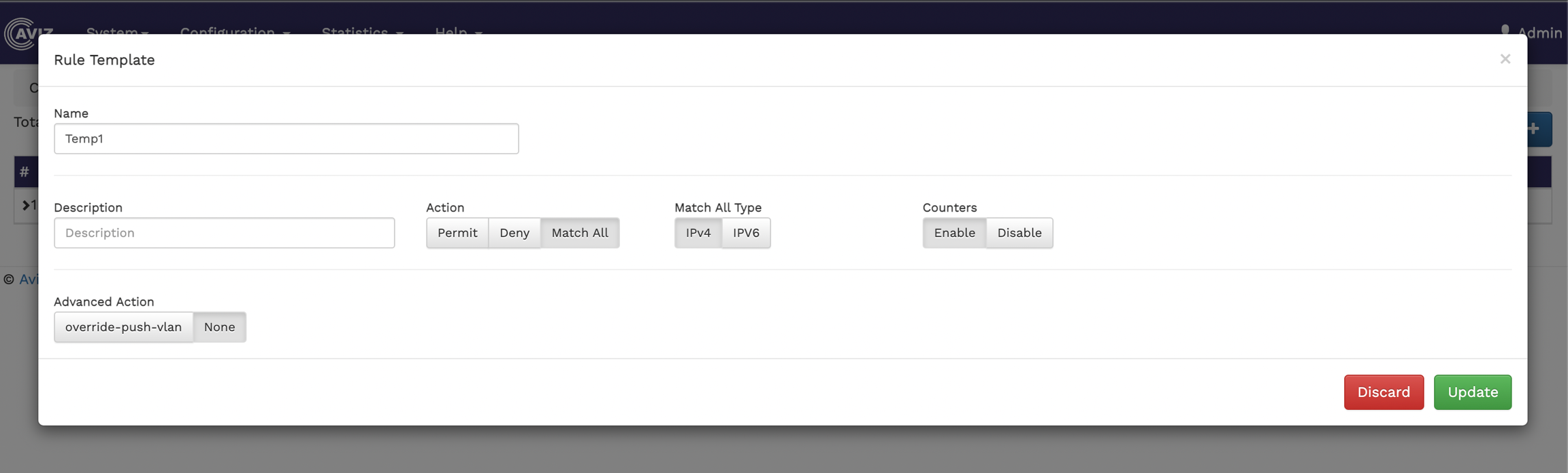
The Rule Templates page shows the total number of existing rule templates and a table showing the details of each of these rule templates, such as the name of the template, the action performed, the override action and also an option to edit or delete a rule template.
The following image shows the Rule Templates page:
To create a new rule template,
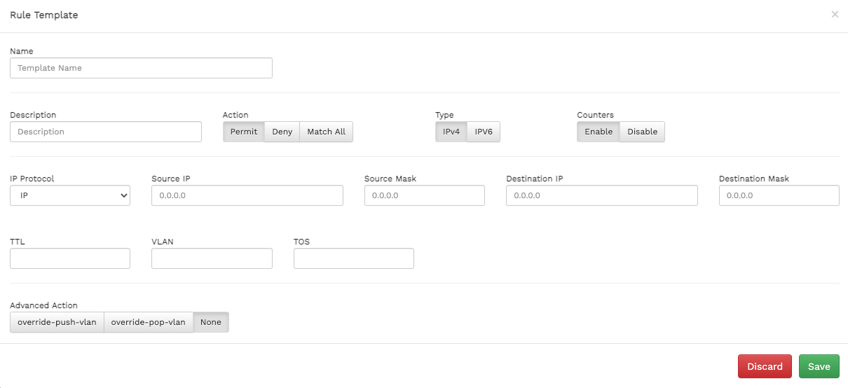
Click the icon at the top right corner of the Rule Templates page. The Rule Template window displays.
Specify values for the following:
Name
To edit an existing rule template, click the icon and make your changes in the Rule Template window.
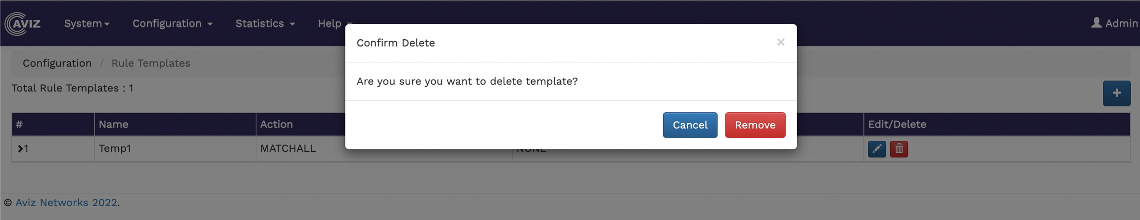
To delete a rule template, click the icon.
Description - enter a description of the new rule template to show its purpose.
Action - select an action for the template. The available options are Permit, Deny, Match All.
Type - select the IP address type. Available options are IPV4 and IPV6.
Counters - enable or disable counters.
IP Protocol - select the IP protocol for the template. The available options are - IP, TCP, UDP.
Source IP - specify the source ip for the template.
Source Mask - specify the source mask for the template.
Destination IP - specify the destination IP for the template.
Destination Mask - specify the destination mask for the template.
TTL - specify the time-to-live value for the packets in the system.
VLAN - specify the VLAN details.
TOS - specify the type of service.
Advanced Action - specify the override actions. The available options are override-push-vlan, override-pop-vlan, and None.
3. Click Save to apply the changes.
To create and configure flows from the FlowVision GUI, click Configuration > Flow Manager.
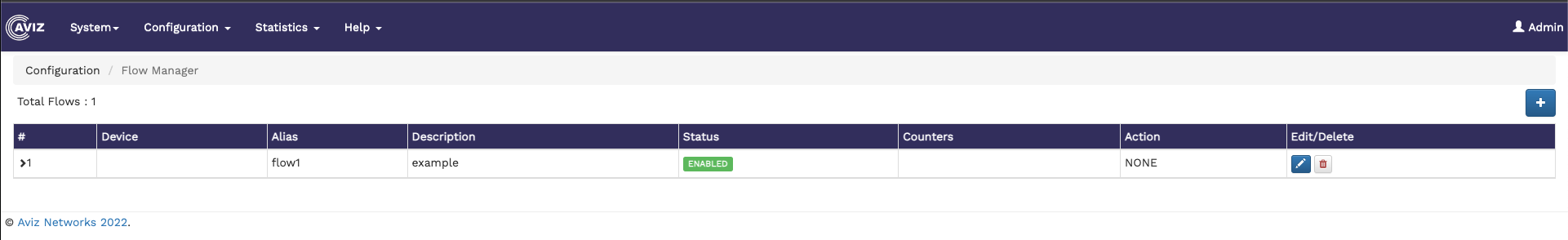
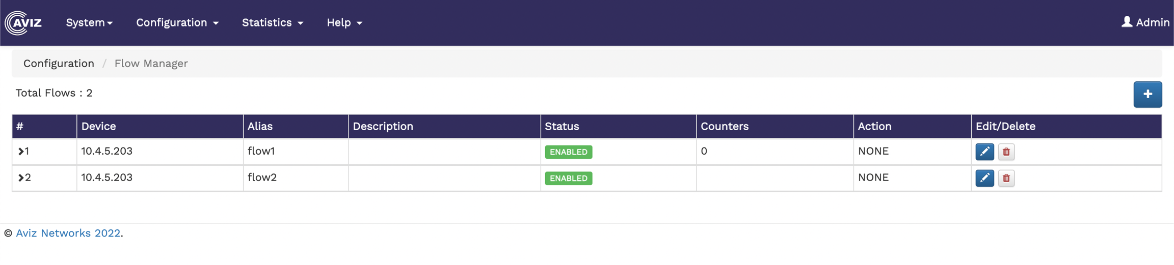
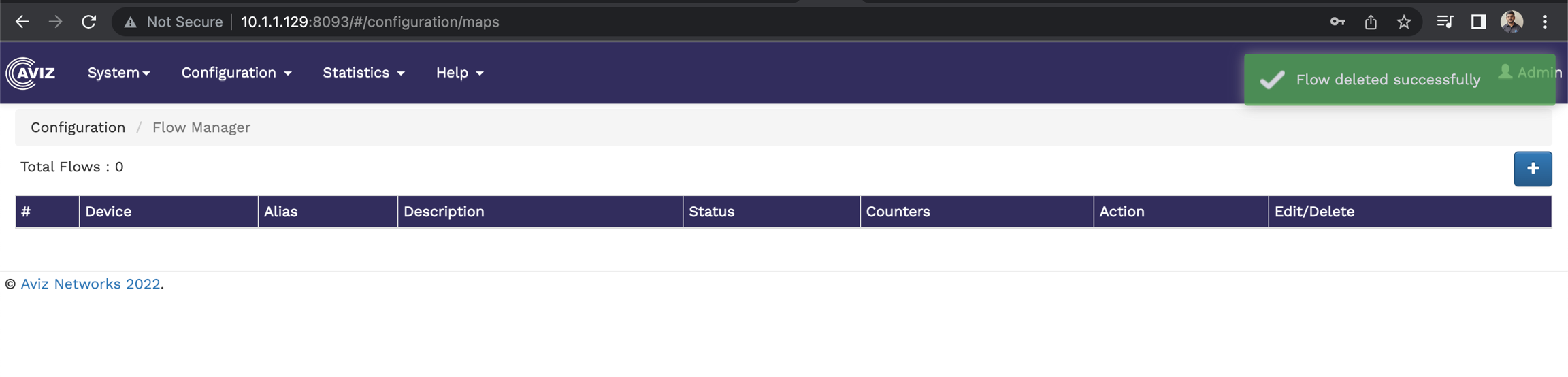
The Flow Manager page shows the number of existing flows and a table showing the flow details, such as, device ID, alias, description of the flow, status, the available counters, the action performed, and an option to edit and delete flows.
The following image shows the Flow Manager page:
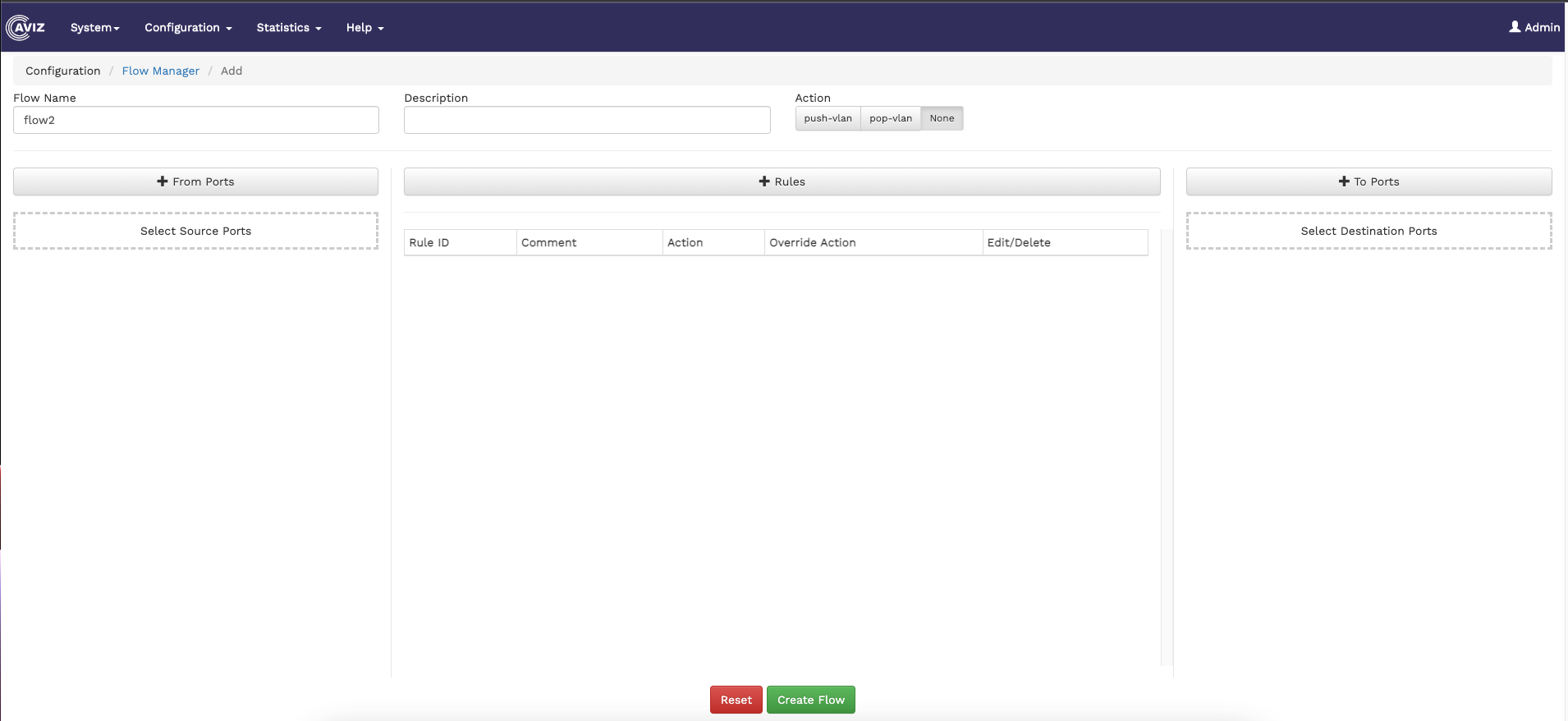
To create a new flow, click the button on the top right corner of the Flow Manager page. The Add Flow page displays.
Specify the Flow Name, Description for the Flow, and select the Action.
To add source ports,
Click the From Ports button on the Add Flow page. The Add From Ports window displays.
Select a device to list all the ports available for that device.
Select the ports you need to add as source ports.
To add rules,
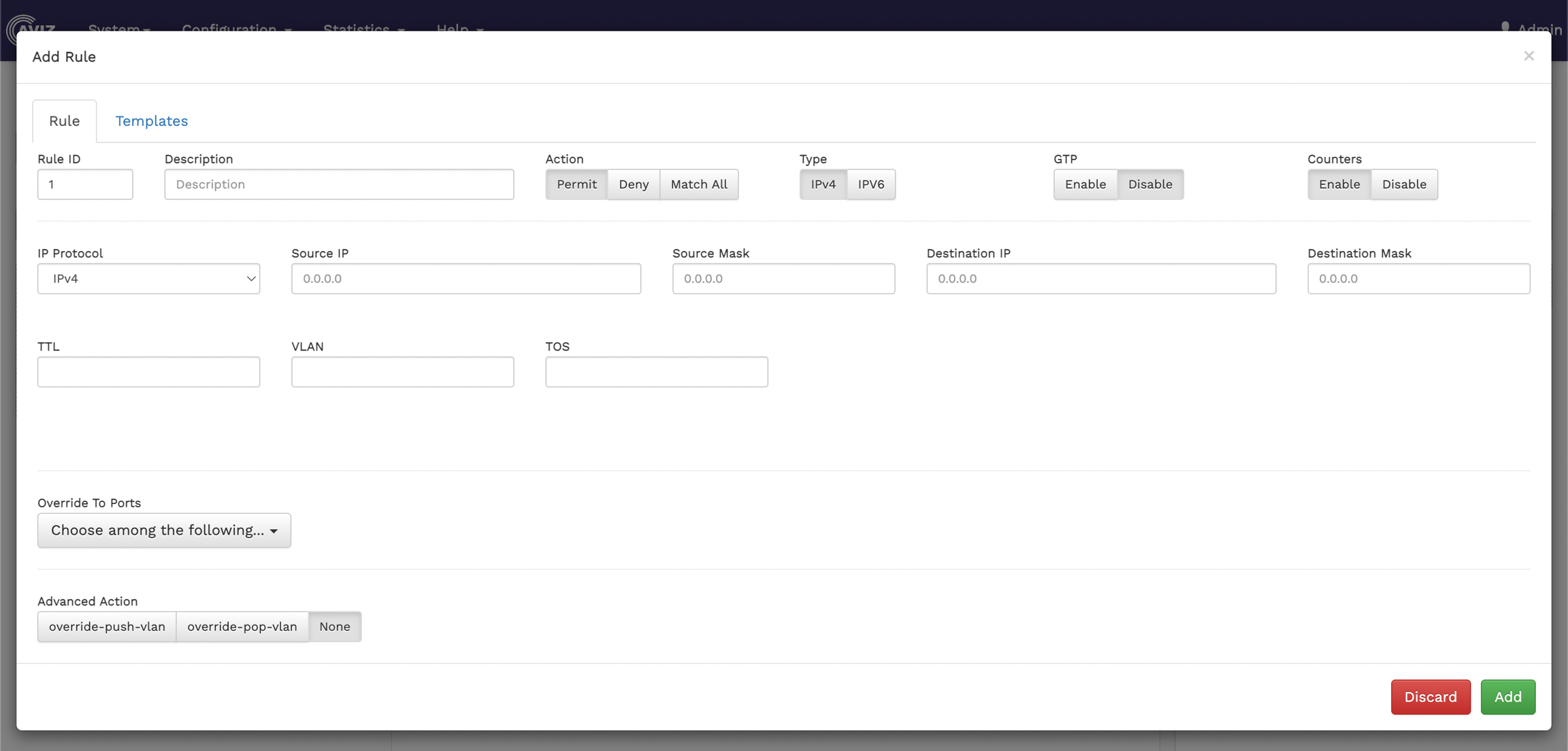
Click the Rules button on the Add Flow page. The Add Rule window displays.
Specify values for the following, in the Rule tab:
The added rules are displayed in the table below the Rules button on the Flow Manager page.
To add destination ports,
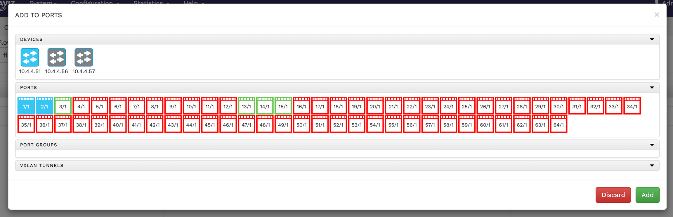
Click the To Ports button on the Add Flow page. The Add To Ports window displays.
Select a device to list all the ports available for that device.
Select the ports you need to add as destination ports.
After adding the source ports, destination ports, and rules, click Create Flow on the Add Flow page. This action creates a new flow.
To edit an existing flow, click the icon and make your changes in the flow page. Once the modification is done, click the update button
To delete the existing flow, click the icon.
Click Add to add the ports to the list of source ports. The added ports are displayed in the field below the From Ports button on the Add Flow page.
Description - enter a description of the new rule to show its purpose.
Action - select an action for the rule. The available options are Permit, Deny, Match All.
Type - select the IP address type. Available options are IPV4 and IPV6.
GTP - enable or disable the GTP-based filter option on a rule
Counters - enable or disable counters.
IP Protocol - select the IP protocol for the rule. The available options are - IP, TCP, and UDP.
Source IP - specify the source IP for the rule.
Source Mask - specify the source mask for the rule.
Destination IP - specify the destination IP for the rule.
Destination Mask - specify the destination mask for the rule.
TTL - specify the time-to-live value for the packets in the system.
VLAN - specify the VLAN details.
TOS - specify the type of service.
Override To Ports - select the override option for ports.
Advanced Action - specify the override actions. The available options are override-push-vlan, override-pop-vlan, and None. If you select override-push-vlan, you must also provide the VLAN ID, in the VLAN ID field.
Specify values in the Template tab. Either specify the rule options in the first tab or select the pre-defined template on the second tab. For details on the template, refer to
Click Add to add the rule.
Click Add to add the ports to the list of destination ports. The added ports are displayed in the field below the To Ports button on the Add Flow page.
To configure the ports of the connected devices from the FlowVision GUI, click Configuration > Ports.
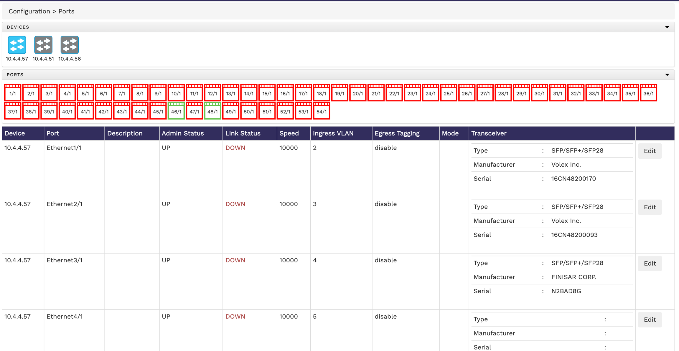
The Ports page shows the connected devices, the ports of each of those connected devices, and a table displaying the details of the ports, such as, the admin status, link status, speed, ingress VLAN, egress tagging, truncation, mode, and the tranceiver details. Note that, the ports that have their link status as 'UP' are shown in green, whereas the ones with the link ststus as 'DOWN' are shown in red. You can hover the mouse pointer over the devices icon or ports icon for more information on that device or port.
By default, when you select a device in the Devices section, the ports table shows you the details of all the ports of the selected device. If you want to get the details of particular ports, click the port number in the Ports section. You can also edit the properties of ports from the ports table.
The following image shows the ports page with device, ports, and port status details:
To edit the properties of a port,
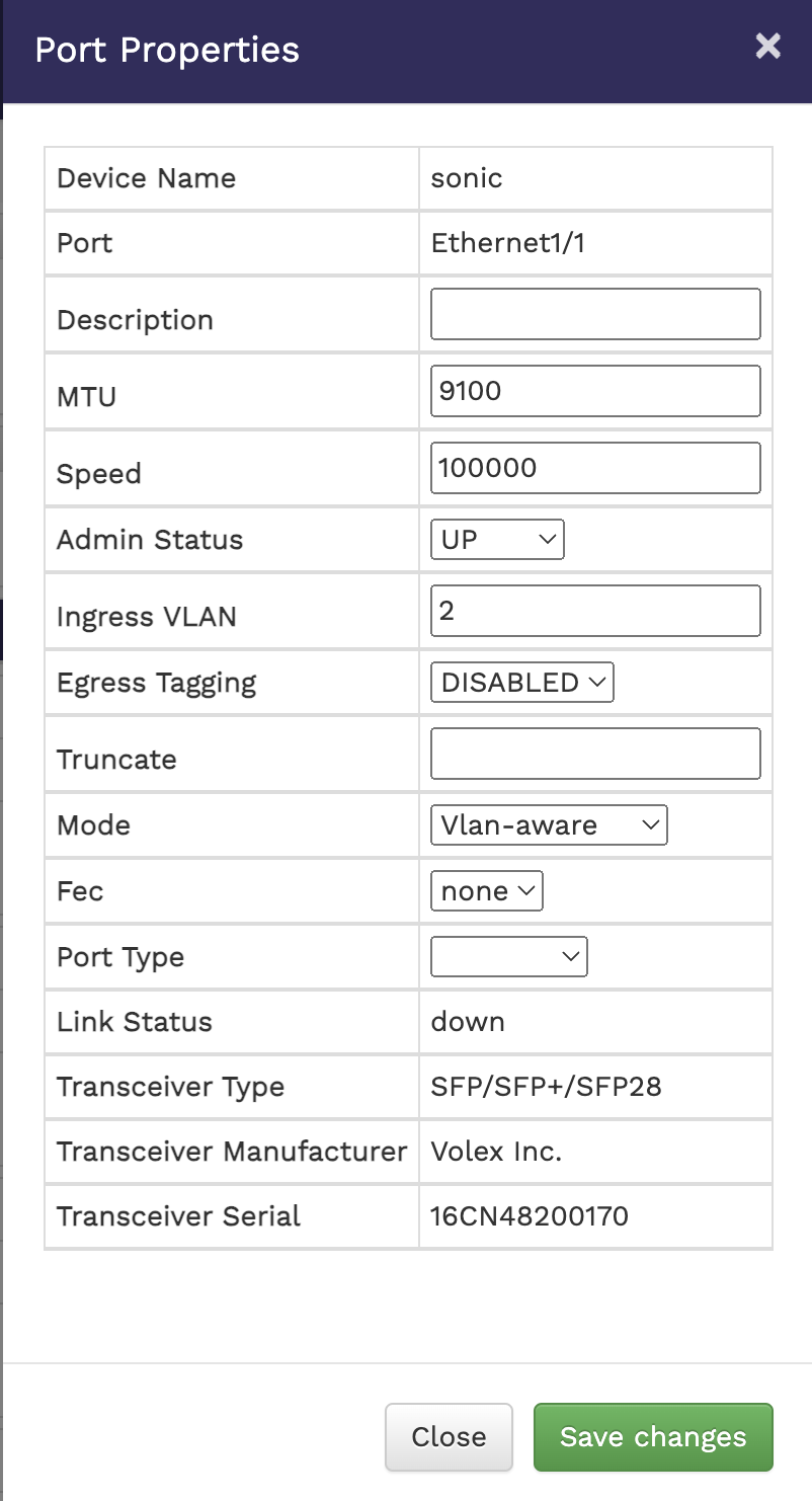
Click the Edit button against the required port in the ports table. The Port Properties window displays.
Update the properties as required. The properties you can update are - Description, MTU, Speed, Admin Status, Ingress VLAN, Egress Tagging, Truncate, Mode, Fec and Port Type. You can also see other non-changeable fields with more information about the selected port.
Click Save Changes to apply your changes.
You can group ports from a device together and create port groups. To get to the port groups page from the FlowVision GUI, click Configuration > Port Groups.
The Port Groups page shows you the connected devices and a table that shows the port groups from each device, the port group ID, the name of the ports that are part of the port group and an option to delete any existing port group.
The following image shows the Port Groups page:
To create a new port group,
Click the icon at the top right corner of the port groups page. The Port Group window displays.
Select the device where you want to create the port group.
Click the required ports to add them to the port group. The added ports are displayed in the Select ports to create Groups
Specify a number i.e. say 1 to 15, for the port group in the Port Group Id field.
Click Save.


The configuration menu helps you perform the following:
