//Network ports
configure terminal
interface ethernet Ethernet12
forward-error-correction rs
type network
end//Tool ports
configure terminal
interface ethernet Ethernet64/72
forward-error-correction rs
type tool
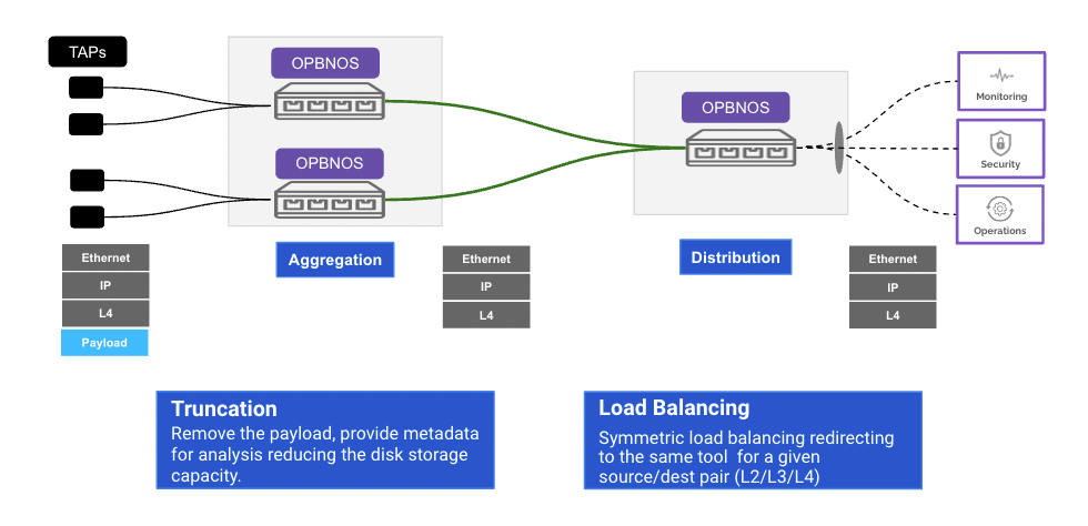
endconfigure terminal
interface ethernet Ethernet12
truncate 64
endconfigure terminal
port-channel 10 ports Ethernet64,Ethernet72
endflow flow2
network-ports Ethernet12
tool-ports port-channel10
rule 1 permit src-ip 1.1.1.1/32 dest-ip 2.2.2.2/32 protocol tcp counters enable
rule 2 permit src-ip 2401::1 src-netmask f::f dest-ip 2401::2 dest-netmask f::f counters enable// verify Truncation
pbnoscli# show interface npb Ethernet12/1
===================================
Interface : Ethernet12/1
===================================
Mode : vlan-aware
Ingress-vlan : 14
Egress-tagging : disable
Truncate : 64
pbnoscli#
// verify port-channel status
pbnoscli# show port-channel information
===================================
Name         : port-channel10
Member ports : Ethernet64/1[up] Ethernet63/1[up]
===================================
pbnoscli# // verify flow
pbnoscli# show flow summary
Flow-Name Rule-Id Status Counter-Value
=========================================================
flow2 2 Active 50414924
flow2 1 Active 50410923
pbnoscli# // verify Loadbalancing
pbnoscli# show interface counters
========================================================================================================================================================================================
Port InOctets InUcastPackets InMcastPackets InBcastPackets OutOctets OutUcastPackets OutMcastPackets OutBcastPackets
========================================================================================================================================================================================
Ethernet1/1 0 0 0 0 0 0 0 0
Ethernet2/1 0 0 0 0 0 0 0 0
Ethernet3/1 0 0 0 0 0 0 0 0
Ethernet4/1 17597009152 68738285 0 0 239 0 1 0
<..>
Ethernet63/1 0 0 0 0 240 0 1 0
Ethernet64/1 0 0 0 0 0 0 0 0
pbnoscli#//Network ports
configure terminal
interface ethernet Ethernet12/1
forward-error-correction rs
type network
end//Tool ports
configure terminal
interface ethernet Ethernet16/1
forward-error-correction rs
type tool
end//Network ports
configure terminal
interface ethernet Ethernet12/1
forward-error-correction rs
type network
exit//Tool ports
configure terminal
interface ethernet Ethernet16/1
forward-error-correction rs
type tool
exitconfigure terminal
interface ethernet Ethernet12/1
ingress-vlan 512
endconfigure terminal
interface ethernet Ethernet16/1
egress-tagging enable
endconfigure terminal
flow flow1
network-ports Ethernet12/1
tool-ports Ethernet16/1
rule 1 permit match-all counters enable
end// verify interface
pbnoscli# show interface npb Ethernet12/1
===================================
Interface : Ethernet12/1
===================================
Mode : vlan-aware
Ingress-vlan : 512
Egress-tagging : disable
pbnoscli# show interface npb Ethernet16/1
===================================
Interface : Ethernet16/1
===================================
Mode : vlan-aware
Ingress-vlan : 18
Egress-tagging : enable// verify flow
pbnoscli# show flow summary
Flow-Name Rule-Id Status Counter-Value
=========================================================
flow1 1 Active 1154
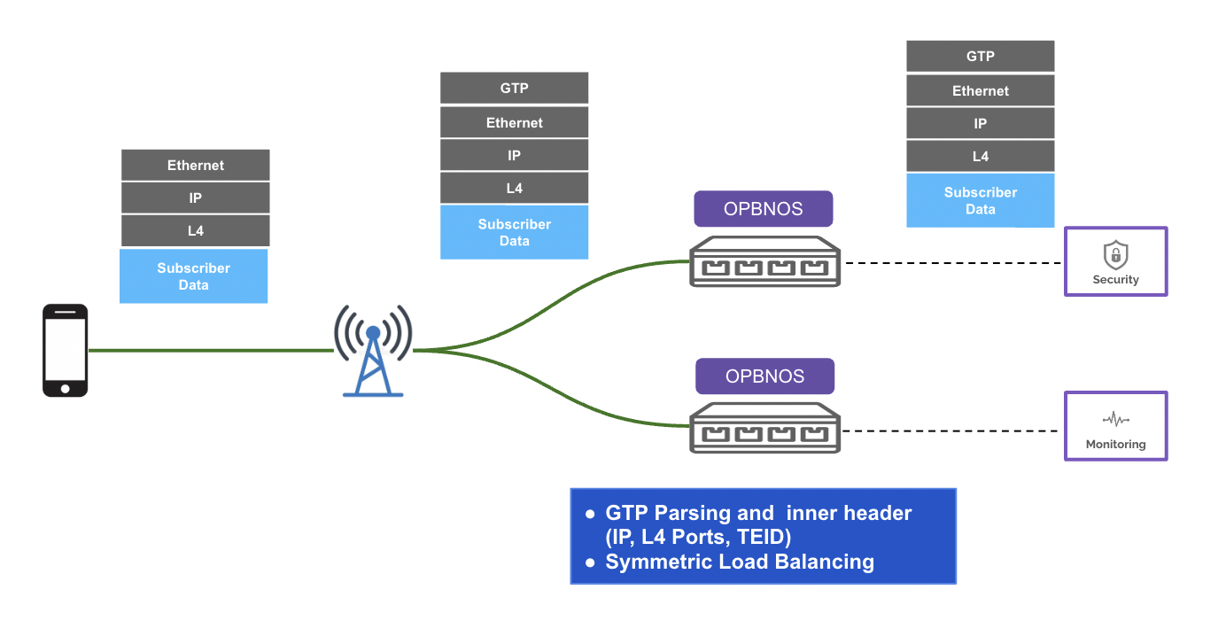
pbnoscli# configure terminal
gtp
exitconfigure terminal
flow flow01
network-ports Ethernet12/1
tool-ports Ethernet16/1
rule 1 permit src-ip 1.1.1.1/32 dest-ip 2.2.2.2/32 gtp "inner-sip 10.0.0.1/24 inner-dip 20.0.0.1/24" counters enable
!pbnoscli# show interface status
================================================================================================
Port Name Oper Admin Vlan Speed MTU AutoNeg
================================================================================================
Ethernet1/1 etp1 up up 100000 9100 on
Ethernet2/1 etp2 up up 100000 9100 on
<..>
Ethernet63/1 etp63 up up 100000 9100 on
Ethernet64/1 etp64 up up 100000 9100 on
pbnoscli# pbnoscli# show flow summary
Flow-Name Rule-Id Status Counter-Value
=========================================================
flow01 1 Active 103511710
pbnoscli# 
pbnoscli(config)# flow swap
pbnoscli(config-flow-swap)# network-ports Ethernet1/1
pbnoscli(config-flow-swap)# tool-ports Ethernet50/1
pbnoscli(config-flow-swap)# rule 5 permit protocol 58 counters enable
pbnoscli(config-flow-swap)# rule 5 action override-to cpu
pbnoscli(config-flow-swap)# rule 6 permit match-all counters enable
pbnoscli(config-flow-swap)# rule 6 action overwrite dest-ip 10.10.10.1 dest-mac 1c:34:da:23:77:00 dest-port 4789
pbnoscli(config-flow-swap)# rule 7 permit match-all ipv6 counters enable
pbnoscli(config-flow-swap)# rule 7 action overwrite dest-mac 1c:34:da:23:77:00 dest-port 4789
pbnoscli(config-flow-swap)# end
pbnoscli#pbnoscli(config)# tunnel tunnel1
pbnoscli(config-tunnel-tunnel1)# ingress-interface Ethernet50/1
pbnoscli(config-tunnel-tunnel1)# strip-vxlan egress Ethernet41/1
pbnoscli(config-tunnel-tunnel1)# source-ip 10.10.10.1
pbnoscli(config-tunnel-tunnel1)# destination-ip 10.10.10.2
pbnoscli(config-tunnel-tunnel1)# vni 4098
pbnoscli(config-tunnel-tunnel1)# vlan-tagging disable
pbnoscli(config-tunnel-tunnel1)# pbnoscli(config)# flow egress
pbnoscli(config-flow-egress)# network-ports Ethernet42/1
pbnoscli(config-flow-egress)# tool-ports Ethernet64/1
pbnoscli(config-flow-egress)# rule 10 permit match-all counters enable
pbnoscli(config-flow-egress)# rule 20 permit match-all ipv6 counters enable
pbnoscli(config-flow-egress)# rule 20 action override-to Ethernet64/1
pbnoscli(config-flow-egress)# end
pbnoscli#pbnoscli# show vxlan tunnel all
===============================================
VXLAN Tunnel - tunnel1
===============================================
Tunnel Port : Ethernet50/1
Source IP : 10.10.10.1
Destination IP : 10.10.10.2
Source MAC : 1c:34:da:23:77:00
VN-ID : 4098
Vlan Tagging : false
Tunnel Status : UP
pbnoscli#OPBNOS# show running-config
configure terminal
interface ethernet Ethernet41/1
mode vlan-aware
mtu 9100
speed 100000
forward-error-correction none
!
interface ethernet Ethernet42/1
mode vlan-aware
mtu 9100
speed 100000
forward-error-correction none
!
interface ethernet Ethernet1/1
mode vlan-aware
loopback-mode
mtu 9100
speed 100000
forward-error-correction none
!
interface ethernet Ethernet50/1
mode vlan-aware
mtu 9100
speed 100000
forward-error-correction none
!
interface ethernet Ethernet64/1
mode vlan-aware
mtu 9100
speed 100000
forward-error-correction none
!
hostname OPBNOS
tunnel tunnel_strip
ingress-interface Ethernet50/1
strip-vxlan egress Ethernet41/1
source-ip 10.10.10.1
destination-ip 10.10.10.2
vni 4098
vlan-tagging disable
!
flow in_vxlan
enable
network-ports Ethernet1/1
tool-ports Ethernet50/1
rule 5 permit protocol 58 counters enable
rule 5 action override-to cpu
rule 6 permit match-all counters enable
rule 6 action overwrite dest-ip 10.10.10.1 dest-mac 1c:34:da:23:77:00 dest-port 4789
rule 7 permit match-all ipv6 counters enable
rule 7 action overwrite dest-mac 1c:34:da:23:77:00 dest-port 4789
end
!
flow egress
enable
network-ports Ethernet42/1
tool-ports Ethernet64/1
rule 10 permit match-all counters enable
rule 20 permit match-all ipv6 counters enable
rule 20 action override-to Ethernet64/1
!
!
OPBNOS#configure terminal
interface ethernet Ethernet64/1
forward-error-correction rs
type network
exitconfigure terminal
interface ethernet Ethernet1/1
forward-error-correction none
type tool
exitconfigure terminal
tunnel tunnel1
interface Ethernet1/1
source-ip 1.1.1.1
destination-ip 1.1.1.2
vni 4099
vlan-tagging disable
exitflow flow1
network-ports Ethernet64/1
tool-ports tunnel1
rule 1 permit match-all counters enable
end//Analyser port - Tool port
configure terminal
interface ethernet Ethernet12/1
forward-error-correction rs
type tool
exit//VxLAN port - Tool port
configure terminal
interface ethernet Ethernet1/1
forward-error-correction none
type tool
exitconfigure terminal
tunnel tunnel2
interface Ethernet1/1
source-ip 1.1.1.2
destination-ip 1.1.1.1
vni 4099
vlan-tagging disable
exitflow flow01
network-ports tunnel1
tool-ports Ethernet12/1
rule 1 permit match-all counters enable
exitpbnoscli# show vxlan tunnel all
===============================================
VXLAN Tunnel - tunnel1
===============================================
Tunnel Port : Ethernet1/1
Source IP : 1.1.1.1
Destination IP : 1.1.1.2
Source MAC : 1c:34:da:23:77:00
VN-ID : 4099
Vlan Tagging : false
pbnoscli#
pbnoscli# show vxlan tunnel all
===============================================
VXLAN Tunnel - tunnel2
===============================================
Tunnel Port : Ethernet1/1
Source IP : 1.1.1.2
Destination IP : 1.1.1.1
Source MAC : 1c:34:da:24:de:00
VN-ID : 4099
Vlan Tagging : false
pbnoscli#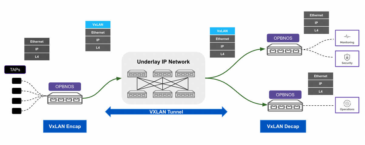
//Tool ports
configure terminal
interface ethernet Ethernet16/1
forward-error-correction rs
type tool
end//Network ports
configure terminal
interface ethernet Ethernet12/1
forward-error-correction rs
type network
endconfigure terminal
interface ethernet Ethernet12/1
type network
mode vlan-aware
endconfigure terminal
interface ethernet Ethernet16/1
egress-tagging enable
type tool
endflow flow1
network-ports Ethernet12/1
tool-ports Ethernet16/1
push-vlan-tag 300
rule 1 permit match-all counters enable
end// verify interface
pbnoscli# show interface npb Ethernet12/1
===================================
Interface : Ethernet12/1
===================================
Type : network
Mode : vlan-aware
Ingress-vlan : 14
Egress-tagging : disable
pbnoscli# show interface npb Ethernet16/1
===================================
Interface : Ethernet16/1
===================================
Mode : vlan-aware
Ingress-vlan : 18
Egress-tagging : enable
pbnoscli# // verify flow
pbnoscli# show flow all
===================================
Flow : flow1 (CLI)
===================================
Status : enable
Network-Port : Ethernet12/1
Tool-Port : Ethernet16/1
Push vlan : 300
Rule : 1
++++++++++++++++++++++++++++++++++
Action : permit
Counters : enable
Match-all : ipv4
pbnoscli# //Tool ports
configure terminal
interface ethernet Ethernet16/1
forward-error-correction rs
type tool
end//Network ports
configure terminal
interface ethernet Ethernet12/1
forward-error-correction rs
type network
endconfigure terminal
interface ethernet Ethernet12/1
type network
mode vlan-aware
endconfigure terminal
interface ethernet Ethernet16/1
type tool
endflow flow1
network-ports Ethernet12/1
tool-ports Ethernet16/1
pop-vlan enable
rule 1 permit match-all counters enable
end// verify interface
pbnoscli# show interface npb Ethernet12/1
===================================
Interface : Ethernet12/1
===================================
Type : network
Mode : vlan-aware
Ingress-vlan : 14
Egress-tagging : disable
pbnoscli# show interface npb Ethernet16/1
===================================
Interface : Ethernet16/1
===================================
Mode : vlan-aware
Ingress-vlan : 18
Egress-tagging : disable
pbnoscli#// verify flow
pbnoscli# show flow all
===================================
Flow : flow1 (CLI)
===================================
Status : enable
Network-Port : Ethernet12/1
Tool-Port : Ethernet16/1
Pop vlan : enable
Rule : 1
++++++++++++++++++++++++++++++++++
Action : permit
Counters : enable
Match-all : ipv4
pbnoscli# 
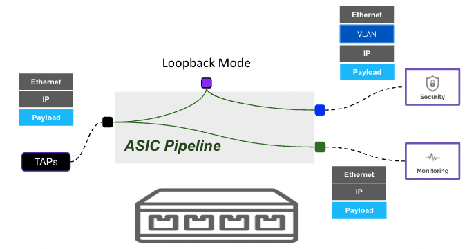
//Tool ports
configure terminal
interface ethernet Ethernet16/1
forward-error-correction rs
type tool
end//Network ports
configure terminal
interface ethernet Ethernet12/1
forward-error-correction rs
type network
endconfigure terminal
interface ethernet Ethernet20/1
loopback-mode
endconfigure terminal
flow flow1
network-ports Ethernet12/1
tool-ports Ethernet20/1
rule 1 permit match-all counters enable
endconfigure terminal
flow flow2
network-ports Ethernet20/1
tool-ports Ethernet16/1
rule 1 permit src-ip 1.1.1.1/32 dest-ip 5.5.5.5/32 counters enable
end// verify interface
pbnoscli# show interface status
================================================================================================
Port Name Oper Admin Vlan Speed MTU AutoNeg
================================================================================================
Ethernet1/1 etp1 down up 100000 9100 on
Ethernet2/1 etp2 down up 100000 9100 on
Ethernet3/1 etp3 down up 100000 9100 on
Ethernet4/1 etp4 up up 25000 9100 on
Ethernet5/1 etp5 up up 25000 9100 on
Ethernet6/1 etp6 up up 100000 9100 on
<..>
Ethernet63/1 etp21 down up 100000 9100 on
Ethernet64/1 etp22 down up 100000 9100 on
pbnoscli#
// verify loopback-mode port
pbnoscli# show interface npb Ethernet20/1
===================================
Interface : Ethernet20/1
===================================
Mode           : vlan-aware
Ingress-vlan   : 22
Egress-tagging : disable
Loopback-mode  : enable

pbnoscli# // verify flow
pbnoscli# show flow summary
Flow-Name Rule-Id Status Counter-Value
=========================================================
flow1 1 Active 11592
flow2 1 Active 590
pbnoscli#