
Loading...
Loading...
Loading...
Loading...
Loading...
Loading...
Loading...
Loading...
Loading...
Loading...
Loading...
Loading...
Loading...
Loading...
Loading...
Loading...
Loading...
Loading...
Loading...
Loading...
Loading...
Loading...
Loading...
Loading...
Loading...
Loading...
Loading...
Loading...
Loading...
Loading...
Loading...
Loading...
Loading...
Loading...
Loading...
Loading...
Loading...
Loading...
Loading...
Loading...
Loading...
Loading...
Loading...
Loading...
Loading...
Loading...
Loading...
Loading...
Loading...
Loading...
Loading...
Loading...
Loading...
Loading...
Loading...
Loading...
Loading...
Loading...
Loading...
Loading...
Loading...
Loading...
Loading...
Loading...
Loading...
Loading...
Loading...
Loading...
Loading...
Loading...
Loading...
Loading...
Loading...
Loading...
Loading...
Loading...
Loading...
Loading...
Loading...
Loading...
Loading...
Loading...
Loading...
Loading...
Loading...
Loading...
Loading...
Loading...
Loading...
Loading...
Loading...
Loading...
Loading...
Loading...
Loading...
Loading...
Loading...
Loading...
Loading...
pbnoscli# configure terminal
pbnoscli(config)# flowvision
enable enable/disable the flowvision tool
pbnoscli(config)# flowvision enable
pbnoscli(config)# pbnoscli# configure terminal
pbnoscli(config)# timestamping
enable enable/disable the OPB Packet Timestamping
pbnoscli(config)# timestamping enable
pbnoscli(config)#
#Disable#
pbnoscli# configure terminal
pbnoscli(config)# timestamping
enable enable/disable the OPB Packet Timestamping
pbnoscli(config)#no timestamping enable
pbnoscli(config)#pbnoscli# show running-config
configure terminal
!
timestamping enable
!
!
pbnoscli#pbnoscli# configure terminal
pbnoscli(config)# interface ethernet Ethernet1/1
pbnoscli(config-if)# timestamp
enable Enable timestamp
pbnoscli(config-if)# timestamp enable
pbnoscli(config-if)# timestamp enable stage
egress Egress
ingress Ingress
pbnoscli(config-if)# timestamp enable stage egress
source-id Specify source id
pbnoscli(config-if)# timestamp enable stage egress source-id 0x8233
pbnoscli(config-if)#end
pbnoscli#
#Disable#
pbnoscli(config-if)# no timestamp enable stage egress source-id 0x8233pbnoscli# show running-config
configure terminal
interface ethernet Ethernet1/1
mtu 9100
speed 25000
timestamp enable stage egress source-id 0x8233
!
timestamping enable
!
!
pbnoscli#pbnoscli# show interface breakout current-mode Ethernet49/1
======================================
Interface Breakout
======================================
Ethernet49/1 1x100G[40G]
pbnoscli# show interface breakout
{
"Ethernet1/1": {
"index": "1",
"lanes": "3",
"breakout_modes": {
"1x25G": [
"Eth1(Port1)"
]
},
"default_brkout_mode": "1x25G",
"Current Breakout Mode": "1x25G",
"child ports": "Ethernet1/1",
"child port speeds": "25G"
},
<skipped>
"Ethernet49/1": {
"index": "49,49,49,49",
"lanes": "77,78,79,80",
"breakout_modes": {
"1x100G[40G]": [
"Eth49(Port49)"
],
"2x50G": [
"Eth49/1(Port49)",
"Eth49/2(Port49)"
],
"4x25G": [
"Eth49/1(Port49)",
"Eth49/2(Port49)",
"Eth49/3(Port49)",
"Eth49/4(Port49)"
],
"4x10G": [
"Eth49/1(Port49)",
"Eth49/2(Port49)",
"Eth49/3(Port49)",
"Eth49/4(Port49)"
]
},
"default_brkout_mode": "1x100G[40G]",
"Current Breakout Mode": "1x100G[40G]",
"child ports": "Ethernet49/1",
"child port speeds": "100G"
}
}
pbnoscli(config)# interface ethernet Ethernet49/1
pbnoscli(config-if)# breakout-mode "4x25G"
Checking for port dependencies....
Configuring interface breakout....
Breakout process got successfully completed!
Reboot is required to apply the breakout changes!
Do you want to save and reboot to apply the changes [y/n]: y
Saving configuration...
Rebooting the device...
//After reboot
pbnoscli# show interface status
================================================================================================
Port Name Oper Admin Vlan Speed MTU AutoNeg
================================================================================================
Ethernet1/1 Eth1(Port1) down up routed 25000 9100 N/A
Ethernet2/1 Eth2(Port2) down up routed 25000 9100 N/A
Ethernet3/1 Eth3(Port3) down up routed 25000 9100 N/A
Ethernet4/1 Eth4(Port4) up up routed 25000 9100 N/A
Ethernet5/1 Eth5(Port5) down up routed 25000 9100 N/A
Ethernet6/1 Eth6(Port6) down up routed 25000 9100 N/A
Ethernet7/1 Eth7(Port7) down up routed 25000 9100 N/A
Ethernet8/1 Eth8(Port8) down up routed 25000 9100 N/A
Ethernet9/1 Eth9(Port9) down up routed 25000 9100 N/A
Ethernet10/1 Eth10(Port10) down up routed 25000 9100 N/A
<skipped>
Ethernet48/1 Eth48(Port48) down up routed 25000 9100 N/A
Ethernet49/1 Eth49/1(Port49) up up routed 25000 9100 N/A
Ethernet49/2 Eth49/2(Port49) up up routed 25000 9100 N/A
Ethernet49/3 Eth49/3(Port49) up up routed 25000 9100 N/A
Ethernet49/4 Eth49/4(Port49) up up routed 25000 9100 N/A
Ethernet50/1 Eth50(Port50) down up routed 100000 9100 N/A
Ethernet51/1 Eth51(Port51) down up routed 100000 9100 N/A
Ethernet52/1 Eth52(Port52) down up routed 100000 9100 N/A
Ethernet53/1 Eth53(Port53) up up routed 100000 9100 N/A
Ethernet54/1 Eth54(Port54) up up routed 100000 9100 N/A
Ethernet55/1 Eth55(Port55) up up routed 100000 9100 N/A
Ethernet56/1 Eth56(Port56) down up routed 100000 9100 N/A
pbnoscli# show running-config
configure terminal
interface ethernet Ethernet1/1
mtu 9100
speed 25000
!
<skipped>
interface ethernet Ethernet48/1
mtu 9100
speed 25000
!
interface ethernet Ethernet49/1
mtu 9100
speed 25000
forward-error-correction none
!
interface ethernet Ethernet49/2
mtu 9100
speed 25000
forward-error-correction none
!
interface ethernet Ethernet49/3
mtu 9100
speed 25000
forward-error-correction none
!
interface ethernet Ethernet49/4
mtu 9100
speed 25000
forward-error-correction none
!
interface ethernet Ethernet50/1
mtu 9100
speed 100000
!
pbnoscli# show interface breakout current-mode Ethernet49/1
======================================
Interface Breakout
======================================
Ethernet49/1 4x25G
pbnoscli# show in summary
============================================================================================================================
Interface Lanes Speed MTU FEC Alias Vlan Oper Admin Type Asym PFC
============================================================================================================================
Ethernet1/1 3 25G 9100 N/A Eth1(Port1) routed down up SFP/SFP+/SFP28 N/A
Ethernet2/1 2 25G 9100 N/A Eth2(Port2) routed down up N/A N/A
Ethernet3/1 4 25G 9100 N/A Eth3(Port3) routed down up N/A N/A
Ethernet4/1 8 25G 9100 N/A Eth4(Port4) routed up up SFP/SFP+/SFP28 N/A
Ethernet5/1 7 25G 9100 N/A Eth5(Port5) routed down up N/A N/A
Ethernet6/1 1 25G 9100 N/A Eth6(Port6) routed down up N/A N/A
Ethernet7/1 5 25G 9100 N/A Eth7(Port7) routed down up N/A N/A
Ethernet8/1 16 25G 9100 N/A Eth8(Port8) routed down up N/A N/A
<skipped>
Ethernet49/1 77 25G 9100 none Eth49/1(Port49) routed up up QSFP28 or later N/A
Ethernet49/2 78 25G 9100 none Eth49/2(Port49) routed up up QSFP28 or later N/A
Ethernet49/3 79 25G 9100 none Eth49/3(Port49) routed up up QSFP28 or later N/A
Ethernet49/4 80 25G 9100 none Eth49/4(Port49) routed up up QSFP28 or later N/A
Ethernet50/1 85,86,87,88 100G 9100 N/A Eth50(Port50) routed down up N/A N/A
Ethernet51/1 93,94,95,96 100G 9100 N/A Eth51(Port51) routed down up N/A N/A
Ethernet52/1 97,98,99,100 100G 9100 N/A Eth52(Port52) routed down up N/A N/A
Ethernet53/1 105,106,107,108 100G 9100 N/A Eth53(Port53) routed up up QSFP28 or later N/A
Ethernet54/1 113,114,115,116 100G 9100 N/A Eth54(Port54) routed up up QSFP28 or later N/A
Ethernet55/1 121,122,123,124 100G 9100 N/A Eth55(Port55) routed up up QSFP28 or later N/A
Ethernet56/1 125,126,127,128 100G 9100 N/A Eth56(Port56) routed down up QSFP28 or later N/A
pbnoscli# configure
pbnoscli(config)# interface ethernet Ethernet49/1
pbnoscli(config-if)# breakout-mode "2x50G"
Checking for port dependencies....
Configuring interface breakout....
Breakout process got successfully completed!
Reboot is required to apply the breakout changes!
Do you want to save and reboot to apply the changes [y/n]: y
Saving configuration...
Rebooting the device...
requested COLD shutdown
// After reboot
pbnoscli# show running-config
configure terminal
interface ethernet Ethernet1/1
mtu 9100
speed 25000
!
interface ethernet Ethernet2/1
mtu 9100
speed 25000
!
<skipped>
interface ethernet Ethernet49/1
mtu 9100
speed 50000
forward-error-correction none
!
interface ethernet Ethernet49/2
mtu 9100
speed 50000
forward-error-correction none
!
interface ethernet Ethernet50/1
mtu 9100
speed 100000
!
pbnoscli# show interface status
================================================================================================
Port Name Oper Admin Vlan Speed MTU AutoNeg
================================================================================================
Ethernet1/1 Eth1(Port1) down up routed 25000 9100 N/A
Ethernet2/1 Eth2(Port2) down up routed 25000 9100 N/A
<skipped>
Ethernet48/1 Eth48(Port48) down up routed 25000 9100 N/A
Ethernet49/1 Eth49/1(Port49) down up routed 50000 9100 N/A
Ethernet49/2 Eth49/2(Port49) down up routed 50000 9100 N/A
Ethernet50/1 Eth50(Port50) down up routed 100000 9100 N/A
Ethernet51/1 Eth51(Port51) down up routed 100000 9100 N/A
Ethernet52/1 Eth52(Port52) down up routed 100000 9100 N/A
Ethernet53/1 Eth53(Port53) up up routed 100000 9100 N/A
Ethernet54/1 Eth54(Port54) up up routed 100000 9100 N/A
Ethernet55/1 Eth55(Port55) up up routed 100000 9100 N/A
Ethernet56/1 Eth56(Port56) down up routed 100000 9100 N/A
pbnoscli# show interface summary
============================================================================================================================
Interface Lanes Speed MTU FEC Alias Vlan Oper Admin Type Asym PFC
============================================================================================================================
Ethernet1/1 3 25G 9100 N/A Eth1(Port1) routed down up SFP/SFP+/SFP28 N/A
<skipped>
Ethernet49/1 77,78 50G 9100 none Eth49/1(Port49) routed down up QSFP28 or later N/A
Ethernet49/2 79,80 50G 9100 none Eth49/2(Port49) routed down up QSFP28 or later N/A
Ethernet50/1 85,86,87,88 100G 9100 N/A Eth50(Port50) routed down up N/A N/A
Ethernet51/1 93,94,95,96 100G 9100 N/A Eth51(Port51) routed down up N/A N/A
Ethernet52/1 97,98,99,100 100G 9100 N/A Eth52(Port52) routed down up N/A N/A
Ethernet53/1 105,106,107,108 100G 9100 N/A Eth53(Port53) routed up up QSFP28 or later N/A
Ethernet54/1 113,114,115,116 100G 9100 N/A Eth54(Port54) routed up up QSFP28 or later N/A
Ethernet55/1 121,122,123,124 100G 9100 N/A Eth55(Port55) routed up up QSFP28 or later N/A
Ethernet56/1 125,126,127,128 100G 9100 N/A Eth56(Port56) routed down up QSFP28 or later N/A
pbnoscli# show interface breakout current-mode Ethernet49/1
======================================
Interface Breakout
======================================
Ethernet49/1 2x50G
pbnoscli# configure terminal
pbnoscli(config)# interface ethernet Ethernet4/1
pbnoscli(config-if)# speed
1000 1G
10000 10G
100000 100G
25000 25G
40000 40G
pbnoscli(config-if)# speed 1000
pbnoscli(config-if)# pbnoscli# show interface summary
============================================================================================================================
Interface Lanes Speed MTU FEC Alias Vlan Oper Admin Type Asym PFC
============================================================================================================================
Ethernet1/1 0,1,2,3 100G 1500 rs etp1 trunk up up QSFP28 or later N/A
Ethernet2/1 8,9,10,11 100G 9100 none etp2 trunk up up QSFP28 or later N/A
Ethernet3/1 16,17,18,19 100G 9100 none etp3 trunk up up QSFP28 or later N/A
Ethernet4/1 24,25,26,27 1G 9100 fs etp4 trunk down up N/A N/A
Ethernet5/1 32,33,34,35 100G 9100 none etp5 trunk down up QSFP28 or later N/A
Ethernet6/1 40,41,42,43 100G 9100 none etp6 trunk down up QSFP28 or later N/A
Ethernet7/1 48,49,50,51 100G 9100 none etp7 trunk down up QSFP28 or later N/A
Ethernet8/1 56,57,58,59 100G 9100 none etp8 trunk down up N/A N/A
Ethernet9/1 64,65,66,67 100G 9100 none etp9 trunk down up N/A N/A
Ethernet10/1 72,73,74,75 100G 9100 none etp10 trunk down up N/A N/A
Ethernet11/1 80,81,82,83 100G 9100 none etp11 trunk down up N/A N/A
Ethernet12/1 88,89,90,91 100G 9100 none etp12 trunk down up N/A N/A
Ethernet13/1 96,97,98,99 100G 9100 none etp13 trunk up up QSFP28 or later N/A
Ethernet14/1 104,105,106,107 100G 9100 none etp14 trunk up up QSFP28 or later N/A
<...>
Ethernet60/1 472,473,474,475 100G 9100 none etp60 trunk down up N/A N/A
Ethernet61/1 480,481,482,483 100G 9100 none etp61 trunk down up N/A N/A
Ethernet62/1 488,489,490,491 100G 9100 none etp62 trunk down up N/A N/A
Ethernet63/1 496,497,498,499 100G 9100 rs etp63 routed up up QSFP28 or later N/A
Ethernet64/1 504,505,506,507 100G 9100 rs etp64 routed up up QSFP28 or later N/A
pbnoscli#pbnoscli# show running-config
configure terminal
!
interface ethernet Ethernet1/1
forward-error-correction rs
!
interface ethernet Ethernet4/1
speed 1000
forward-error-correction fs
!
interface mgmt
ip address 10.4.4.53/23 gateway 10.4.4.1
!
pbnoscli# pbnoscli# configure terminal
pbnoscli(config)# interface ethernet Ethernet4/1
pbnoscli(config-if)# tr
transmit-only Activate tx-only mode
pbnoscli(config-if)# transmit-only
pbnoscli(config-if)# endpbnoscli# show interface npb Ethernet4/1
===================================
Interface : Ethernet4/1
===================================
Ingress-vlan : 18
Egress-tagging : disable
Transmit-only : enable
pbnoscli#pbnoscli# show running-config
configure terminal
interface ethernet Ethernet4/1
transmit-only
!
interface mgmt
ip address 10.4.4.53/23 gateway 10.4.4.1
!
pbnoscli# pbnoscli# configure terminal
pbnoscli(config)# flow flow01
pbnoscli(config-flow-flow01)# network-
network-ports Configure network or TAP ports
pbnoscli(config-flow-flow01)# network-ports Ethernet1/1,Ethernet2/1
pbnoscli(config-flow-flow01)#
Network port as Port-channel
~~~~~~~~~~~~~~~~~~~~~~~~~~~~
pbnoscli# conf t
pbnoscli(config)# flow flow02
pbnoscli(config-flow-flow02)# network-ports
<network_port> Add Network ports (delimited by ,)
pbnoscli(config-flow-flow02)# network-ports port-channel5
pbnoscli(config-flow-flow02)# end
pbnoscli#pbnoscli# show flow flow01
===================================
Flow : flow01 (CLI)
===================================
Status : enable
Network-Port : Ethernet1/1,Ethernet2/1
pbnoscli#
pbnoscli# show flow flow02
===================================
Flow : flow02 (CLI)
===================================
Status : enable
Network-Port : port-channel5
pbnoscli#pbnoscli# show running-config
configure terminal
!
interface ethernet Ethernet1/1
forward-error-correction rs
type network
!
interface ethernet Ethernet2/1
forward-error-correction rs
type network
!
interface mgmt
ip address 10.4.4.53/23 gateway 10.4.4.1
!
flow flow01
network-ports Ethernet0,Ethernet4
!
pbnoscli#
pbnoscli# show running-config
configure terminal
!
port-channel 5 ports Ethernet1/1,Ethernet2/1 lacp min-links 1
!
flow flow02
enable
network-ports port-channel5
pbnoscli#pbnoscli# configure terminal
pbnoscli(config)# flow flow01
pbnoscli(config-flow-flow01)#
! Exit from the current prompt
description Configure description for flow
enable Enable the flow
end Exit to exec prompt
exit Exit from the current prompt
network-ports Configure network or TAP ports
no no form
pop-vlan Pop Vlan Tag
push-vlan-tag Push VLAN tag
rule Configure rule
show Show commands
tool-ports Configure network tool or analyzer ports
top Exit to the configuration prompt
pbnoscli(config-flow-flow01)# rule 1
action Add rule specific action
deny Deny traffic
permit Permit traffic
pbnoscli(config-flow-flow01)# rule 1 permit
<cr>
counters Enable counters
description Add description within double quotes
dest-ip Destination IP address
dscp Differentiated services code point
ethertype ethernet type, 0x800, 0x8100
gtp GTP Tunneling
l4portdst L4 destination port
l4portsrc L4 source port
match-all Match all
protocol IP protocol
qualifiers Flow Rule Qualifiers
src-ip Source IP address
tcpctl TCP Control Flags
tosval Type of Service
ttl Time-to-live
vlan Vlan Identifier
pbnoscli(config-flow-flow01)# rule 1 permit src-ip 10.10.0.0/24 dest-ip 20.0.20.0/24 counters enable
//to remove a rule
pbnoscli(config-flow-flow01)# no rule 1
pbnoscli(config-flow-flow01)#pbnoscli# show flow summary
Flow-Name Rule-Id Status Counter-Value
=========================================================
flow01 1 Active 1675
pbnoscli#
pbnoscli# show flow flow01
===================================
Flow : flow01 (CLI)
===================================
Status : enable
Network-Port : Ethernet1/1,Ethernet2/1
Tool-Port : port-channel1,Ethernet8/1
Rule : 1
++++++++++++++++++++++++++++++++++
Action : permit
Source IP : 2401::1
Source Mask : f::f
Destination IP : 2401::2
Destination Mask : f::f
Counters : enable
pbnoscli# \\Configuring IPv4 rules
pbnoscli# show running-config
configure terminal
port-channel 1 ports Ethernet63/1,Ethernet64/1
!
interface ethernet Ethernet1/1
forward-error-correction rs
type network
!
interface ethernet Ethernet2/1
forward-error-correction rs
type network
!
interface mgmt
ip address 10.4.4.53/23 gateway 10.4.4.1
!
flow flow01
description "--Flow Description--"
network-ports Ethernet1/1,Ethernet2/1
tool-ports port-channel1,Ethernet8/1
rule 1 permit src-ip 10.10.0.0/24 dest-ip 20.0.20.0/24 counters enable
!
pbnoscli# \\Configuring IPv6 rules
pbnoscli# show running-config
configure terminal
port-channel 1 ports Ethernet63/1,Ethernet64/1
!
interface ethernet Ethernet1/1
forward-error-correction rs
type network
!
interface ethernet Ethernet2/1
forward-error-correction rs
type network
!
interface mgmt
ip address 10.4.4.53/23 gateway 10.4.4.1
!
flow flow01
description "--Flow Description--"
network-ports Ethernet1/1,Ethernet2/1
tool-ports port-channel1,Ethernet8/1
rule 1 permit src-ip 2401::1 src-netmask f::f dest-ip 2401::2 dest-netmask f::f counters enable
!
pbnoscli# pbnoscli# configure terminal
pbnoscli(config)# flow flow01
pbnoscli(config-flow-flow01)# descript
description Configure description for flow
pbnoscli(config-flow-flow01)# description "--Flow Description--"
pbnoscli(config-flow-flow01)#
//to remove flow description
pbnoscli(config-flow-flow01)# no description
pbnoscli(config-flow-flow01)# pbnoscli# configure terminal
pbnoscli(config)# flow flow01
pbnoscli(config-flow-flow01)#
! Exit from the current prompt
description Configure description for flow
enable Enable the flow
end Exit to exec prompt
exit Exit from the current prompt
network-ports Configure network or TAP ports
no no form
pop-vlan Pop Vlan Tag
push-vlan-tag Push VLAN tag
rule Configure rule
show Show commands
tool-ports Configure network tool or analyzer ports
top Exit to the configuration prompt
pbnoscli(config-flow-flow01)# exit
//to delete a flow
pbnoscli(config)# no flow flow01
pbnoscli(config)pbnoscli# configure terminal
pbnoscli(config)# flow flow01
pbnoscli(config-flow-flow01)#
! Exit from the current prompt
description Configure description for flow
enable Enable the flow
end Exit to exec prompt
exit Exit from the current prompt
network-ports Configure network or TAP ports
no no form
rule Configure rule
show Show commands
tool-ports Configure network tool or analyzer ports
top Exit to the configuration prompt
pbnoscli(config-flow-flow01)# rule 1
action Add rule specific action
deny Deny traffic
ipv6 IPv6 Rule
permit Permit traffic
pbnoscli(config-flow-flow01)# rule 1 ipv6
deny Deny traffic
permit Permit traffic
pbnoscli(config-flow-flow01)# rule 1 ipv6
pbnoscli(config-flow-flow01)# rule 1 permit
<cr>
counters Enable counters
description Add description within double quotes
dest-ip Destination IP address
dscp Differentiated services code point
ethertype ethernet type, 0x800, 0x8100
l4portdst L4 destination port
l4portsrc L4 source port
match-all Match all
protocol IP protocol
src-ip Source IP address
tcpctl TCP Control Flags
tosval Type of Service
ttl Time-to-live
vlan Vlan Identifier
pbnoscli(config-flow-flow01)# rule 1 permit src-ip 10.10.0.0/24 dest-ip 20.0.20.0/24 counters enable
//to remove a rule
pbnoscli(config-flow-flow01)# no rule 1
pbnoscli(config-flow-flow01)#pbnoscli# show flow summary
Flow-Name Rule-Id Status Counter-Value
=========================================================
flow01 1 Active 1671
pbnoscli# show flow flow01
===================================
Flow : flow01 (CLI)
===================================
Status : enable
Network-Port : Ethernet1/1,Ethernet2/1
Tool-Port : port-channel1,Ethernet8/1
Rule : 1
++++++++++++++++++++++++++++++++++
Action : permit
Source IP : 10.10.0.0
Source Mask : 255.255.255.0
Destination IP : 20.0.20.0
Destination Mask : 255.255.255.0
Counters : enable
pbnoscli# \\Configuring IPv4 rules
pbnoscli# show running-config
configure terminal
port-channel 1 ports Ethernet63/1,Ethernet64/1
!
interface ethernet Ethernet1/1
forward-error-correction rs
type network
!
interface ethernet Ethernet2/1
forward-error-correction rs
type network
!
interface mgmt
ip address 10.4.4.53/23 gateway 10.4.4.1
!
flow flow01
description "--Flow Description--"
network-ports Ethernet1/1,Ethernet2/1
tool-ports port-channel1,Ethernet8/1
rule 1 permit src-ip 10.10.0.0/24 dest-ip 20.0.20.0/24 counters enable
!
pbnoscli# \\Configuring IPv6 rules
pbnoscli# show running-config
configure terminal
port-channel 1 ports Ethernet63/1,Ethernet64/1
!
interface ethernet Ethernet1/1
forward-error-correction rs
type network
!
interface ethernet Ethernet2/1
forward-error-correction rs
type network
!
interface mgmt
ip address 10.4.4.53/23 gateway 10.4.4.1
!
flow flow01
description "--Flow Description--"
network-ports Ethernet1/1,Ethernet2/1
tool-ports port-channel1,Ethernet8/1
rule 1 ipv6 permit src-ip 2401::1 src-netmask f::f dest-ip 2401::2 dest-netmask f::f counters enable
!
pbnoscli# pbnoscli# show flow flow01
===================================
Flow : flow01 (CLI)
===================================
Status : enable
Description : --Flow Description--
pbnoscli# pbnoscli# show running-config
configure terminal
!
interface mgmt
ip address 10.4.4.53/23 gateway 10.4.4.1
!
flow flow01
description "--Flow Description--"
!
pbnoscli# pbnoscli# configure terminal
pbnoscli(config)# flow flow01
pbnoscli(config-flow-flow01)#
! Exit from the current prompt
description Configure description for flow
enable Enable the flow
end Exit to exec prompt
exit Exit from the current prompt
network-ports Configure network or TAP ports
no no form
pop-vlan Pop Vlan Tag
push-vlan-tag Push VLAN tag
rule Configure rule
show Show commands
tool-ports Configure network tool or analyzer ports
top Exit to the configuration prompt
pbnoscli(config-flow-flow01)# rule 1 permit description "Match Expression"
<cr>
counters Enable counters
dest-ip Destination IP address
dscp Differentiated services code point
ethertype ethernet type, 0x800, 0x8100
gtp GTP Tunneling
l4portdst L4 destination port
l4portsrc L4 source port
match-all Match all
match-expression Flow Rule Qualifiers
protocol IP protocol
src-ip Source IP address
tcpctl TCP Control Flags (maximum value is 0x3f)
tosval Type of Service
ttl Time-to-live
udf-data User Defined Data
vlan Vlan Identifier
pbnoscli(config-flow-flow01)# rule 1 permit description "Match Expression"
pbnoscli(config-flow-flow01)# $Match Expression" match-expression
<matchexpression> Example qualifiers: ethertype, vlan, src-ip, src-netmask,
dest-ip, dest-netmask, protocol, l4portsrc,
l4portdst, tosval, dscp, ttl, tcpctl, tcpctlmask,
teid, inner-sip, inner-dip, inner-protocol,
inner_l4srcport, inner_l4destport
pbnoscli(config-flow-flow01)# $Match Expression" match-expression "vlan 100 src-ip 1.1.1.1/32 dest-ip 2.2.2.2/32 protocol udp inner-sip 10.10.10.1/32 inner-dip 20.20.20.2/32" counters enable
pbnoscli(config-flow-flow01)# endpbnoscli# show flow all
===================================
Flow : flow01 (CLI)
===================================
Status : enable
Network-Port : Ethernet1/1,Ethernet2/1
Tool-Port : port-channel1,Ethernet8/1
Rule : 1
++++++++++++++++++++++++++++++++++
Vlan : 100
Source IP : 1.1.1.1
Source Mask : 255.255.255.255
Destination IP : 2.2.2.2
Destination Mask : 255.255.255.255
Protocol : udp
Inner Source IP : 10.10.10.1
Inner Source Mask : 255.255.255.255
Inner Destination IP : 20.20.20.2
Inner Destination Mask : 255.255.255.255
Action : permit
Description : Match Expression
Counters : enable
pbnoscli#
pbnoscli# show flow counters all
Flow-Name Rule-Id ASIC-Stat-Id Counter-Value
=============================================================
flow01 DropRule 40960 42156085
flow01 1 57344 455049065
pbnoscli#pbnoscli# show running-config
configure terminal
!
interface ethernet Ethernet1/1
forward-error-correction rs
type network
!
interface ethernet Ethernet2/1
forward-error-correction rs
type tool
!
interface mgmt
ip address 10.4.4.53/23 gateway 10.4.4.1
!
port-channel 1 ports Ethernet63/1,Ethernet64/1
flow flow01
network-ports Ethernet16
tool-ports Ethernet20
rule 1 permit description "Match Expression" match-expression "vlan 100 src-ip 1.1.1.1/32 dest-ip 2.2.2.2/32 protocol udp inner-sip 10.10.10.1/32 inner-dip 20.20.20.2/32" counters enable
!
pbnoscli# pbnoscli# configure terminal
pbnoscli(config)# flow flow01
pbnoscli(config-flow-flow01)#
! Exit from the current prompt
description Configure description for flow
enable Enable the flow
end Exit to exec prompt
exit Exit from the current prompt
network-ports Configure network or TAP ports
no no form
pop-vlan Pop Vlan Tag
push-vlan-tag Push VLAN tag
rule Configure rule
show Show commands
tool-ports Configure network tool or analyzer ports
top Exit to the configuration prompt
pbnoscli(config-flow-flow01)# rule 1 permit description "UDF" udf-data 0xb166 udf-extraction-group l2 udf-offset 2 counters enable
pbnoscli(config-flow-flow01)# rule 2 permit description "UDF" udf-data 0x4500 udf-extraction-group l3 udf-extraction-point ipv4 udf-offset 0 counters enable
pbnoscli(config-flow-flow01)# endpbnoscli# show flow all
===================================
Flow : flow01 (CLI)
===================================
Status : enable
Network-Port : Ethernet1/1
Tool-Port : Ethernet2/1
Rule : 1
++++++++++++++++++++++++++++++++++
Action : permit
Description : UDF
UDF Data : 0xb166
UDF Extraction Group : l2
UDF Offset : 2
Counters : enable
Rule : 2
++++++++++++++++++++++++++++++++++
Action : permit
Description : UDF
UDF Data : 0x4500
UDF Extraction Group : l3
UDF Extraction Point : ipv4
UDF Offset : 0
Counters : enable
pbnoscli#
pbnoscli# show flow counters all
Flow-Name Rule-Id ASIC-Stat-Id Counter-Value
=============================================================
flow01 2 98304 503378220
flow01 DropRule 73728 4390145
flow01 1 90112 2270112825
pbnoscli# pbnoscli# show running-config
configure terminal
!
interface ethernet Ethernet1/1
forward-error-correction rs
type network
!
interface ethernet Ethernet2/1
forward-error-correction rs
type tool
!
interface mgmt
ip address 10.4.4.53/23 gateway 10.4.4.1
!
flow flow01
network-ports Ethernet1/1
tool-ports Ethernet2/1
rule 1 permit description "UDF" udf-data 0xb166 udf-extraction-group l2 udf-offset 2 counters enable
rule 2 permit description "UDF" udf-data 0x4500 udf-extraction-group l3 udf-extraction-point ipv4 udf-offset 0 counters enable
!
pbnoscli# pbnoscli# configure terminal
pbnoscli(config)# flow flow01
pbnoscli(config-flow-flow01)# network-ports Ethernet4
pbnoscli(config-flow-flow01)# tool-ports Ethernet8
pbnoscli(config-flow-flow01)# rule 1
action Add rule specific action
deny Deny traffic
permit Permit traffic
pbnoscli(config-flow-flow01)# rule 1 action
<cr>
override-pop-vlan Override action to pop the VLAN
override-push-vlan-tag Override action to push VLAN Tag
override-to Override to configure a rule specific network tool or analyzer ports
pbnoscli(config-flow-flow01)# rule 1 action override-to Ethernet12pbnoscli# show flow all
===================================
Flow : flow01 (CLI)
===================================
Status : enable
Network-Port : Ethernet4/1
Tool-Port : Ethernet8/1
Rule : 1
++++++++++++++++++++++++++++++++++
Action : permit
Source IP : 10.10.0.0
Source Mask : 255.255.255.0
Destination IP : 20.0.20.0
Destination Mask : 255.255.255.0
Counters : enable
Override To : Ethernet12/1
pbnoscli# pbnoscli# show running-config
configure terminal
!
interface ethernet Ethernet1/1
forward-error-correction rs
type network
!
interface ethernet Ethernet4/1
forward-error-correction rs
type network
!
interface ethernet Ethernet8/1
forward-error-correction rs
type tool
!
interface ethernet Ethernet12/1
forward-error-correction rs
type tool
!
interface mgmt
ip address 10.4.4.53/23 gateway 10.4.4.1
!
flow flow01
network-ports Ethernet1/1,Ethernet4/1
tool-ports Ethernet8/1
rule 1 permit src-ip 10.10.0.0/24 dest-ip 20.0.20.0/24 counters enable
rule 1 action override-to Ethernet12/1
!
pbnoscli# pbnoscli# configure terminal
pbnoscli(config)# flow flow01
pbnoscli(config-flow-flow01)# network-ports Ethernet1/1,Ethernet2/1
pbnoscli(config-flow-flow01)# tool-
tool-ports Configure network tool or analyzer ports
pbnoscli(config-flow-flow01)# tool-ports port-channel1,Ethernet8/1
pbnoscli(config-flow-flow01)#pbnoscli# show flow flow01
===================================
Flow : flow01 (CLI)
===================================
Status : enable
Network-Port : Ethernet1/1,Ethernet2/1
Tool-Port : port-channel1,Ethernet8/1
pbnoscli# pbnoscli# show running-config
configure terminal
port-channel 1 ports Ethernet63/1,Ethernet64/1
!
interface ethernet Ethernet1/1
forward-error-correction rs
type network
!
interface ethernet Ethernet2/1
forward-error-correction rs
type network
!
interface mgmt
ip address 10.4.4.53/23 gateway 10.4.4.1
!
flow flow01
network-ports Ethernet1/1,Ethernet2/1
tool-ports port-channel1,Ethernet8/1
!
pbnoscli# pbnoscli# configure terminal
pbnoscli(config)# flow flow01
pbnoscli(config-flow-flow01)# push-vlan-tag
<pushvlanid> Add VLAN tag (1...4094)
pbnoscli(config-flow-flow01)# push-vlan-tag 1002
pbnoscli(config-flow-flow01)#
//to remove push tag
pbnoscli(config-flow-flow01)# no push-vlan-tag
pbnoscli(config-flow-flow01)# pbnoscli# show flow flow01
===================================
Flow : flow01 (CLI)
===================================
Status : enable
Network-Port : Ethernet1/1,Ethernet2/1
Tool-Port : Ethernet8/1
Push vlan : enable
pbnoscli# pbnoscli# show running-config
configure terminal
!
interface ethernet Ethernet1/1
forward-error-correction rs
type network
!
interface ethernet Ethernet2/1
forward-error-correction rs
type network
!
interface ethernet Ethernet8/1
forward-error-correction rs
type tool
!
interface mgmt
ip address 10.4.4.53/23 gateway 10.4.4.1
!
flow flow01
network-ports Ethernet1/1,Ethernet2/1
tool-ports Ethernet8/1
push-vlan-tag 1002
rule 10 permit match-all counters enable
rule 20 permit match-all ipv6 counters enable
!
pbnoscli# pbnoscli# configure terminal
pbnoscli(config)# flow flow01
pbnoscli(config-flow-flow01)# pop-vlan
disable Disable Vlan stripping
enable Enable Vlan stripping
pbnoscli(config-flow-flow01)# pop-vlan enable
pbnoscli(config-flow-flow01)#
//to disable pop-vlan
pbnoscli(config-flow-flow01)# pop-vlan disable
pbnoscli(config-flow-flow01)# pbnoscli# show flow flow01
===================================
Flow : flow01 (CLI)
===================================
Status : enable
Network-Port : Ethernet1/1,Ethernet2/1
Tool-Port : Ethernet8/1
Pop vlan : enable
pbnoscli# pbnoscli# show running-config
configure terminal
!
interface ethernet Ethernet1/1
forward-error-correction rs
type network
!
interface ethernet Ethernet2/1
forward-error-correction rs
type network
!
interface ethernet Ethernet8/1
forward-error-correction rs
type tool
!
interface mgmt
ip address 10.4.4.53/23 gateway 10.4.4.1
!
flow flow01
network-ports Ethernet1/1,Ethernet4/1
tool-ports Ethernet8/1
pop-vlan enable
rule 10 permit match-all counters enable
rule 20 permit match-all ipv6 counters enable
!
pbnoscli# EC5812# show flow summary
Flow-Name Rule-Id Status Counter-Value
=========================================================
flow_001 2 Active 0
flow_001 3 Active 0
flow_001 1 Active 0
flow_001 4 Active 0
EC5812# collect-flow-stats
EC5812# show flow summary
Flow-Name Rule-Id Status Counter-Value
=========================================================
flow_001 2 Active 68409729060
flow_001 3 Active 68409744544
flow_001 1 Active 68409756710
flow_001 4 Active 68409769302pbnoscli# show flow counters all rate
Flow-Name Rate (BPS) Rate (PPS)
===============================================================
flow1 0.15 B/s 0.00 P/s
pbnoscli#pbnoscli# show flow all
===================================
Flow : flow01 (CLI)
===================================
Status : enable
Network-Port : Ethernet4/1
Tool-Port : Ethernet8/1
Rule : 1
++++++++++++++++++++++++++++++++++
Action : permit
Source IP : 10.10.0.0
Source Mask : 255.255.255.0
Destination IP : 20.0.20.0
Destination Mask : 255.255.255.0
Counters : enable
Override To : Ethernet12/1
===================================
Flow : flow02 (CLI)
===================================
Status : enable
Network-Port : Ethernet16/1
Tool-Port : Ethernet20/1
Rule : 1
++++++++++++++++++++++++++++++++++
Action : permit
Source IP : 2401::1
Source Mask : f::f
Destination IP : 2401::2
Destination Mask : f::f
TTL : 30
Protocol : tcp
Tosval : 4
Counters : enable
pbnoscli# pbnoscli# show flow flow02 rule 1
===================================
Flow : flow02 (CLI)
===================================
Status : enable
Network-Port : Ethernet16/1
Tool-Port : Ethernet20/1
Rule : 1
++++++++++++++++++++++++++++++++++
Action : permit
Source IP : 2401::1
Source Mask : f::f
Destination IP : 2401::2
Destination Mask : f::f
TTL : 30
Protocol : tcp
Tosval : 4
Counters : enable
pbnoscli# pbnoscli# show flow summary
Flow-Name Rule-Id Status Counter-Value
=========================================================
flow01 1 Active 5643
flow02 1 Active 18236
pbnoscli# pbnoscli# show flow counters all
Flow-Name Rule-Id ASIC-Stat-Id Counter-Value
=============================================================
flow02 1 65536 18236
flow01 1 40960 5643
flow02 DropRule 57344 14
flow01 DropRule 32768 18
pbnoscli# pbnoscli# show flow counters flow01
Flow-Name Rule-Id ASIC-Stat-Id Counter-Value
=============================================================
flow01 1 40960 5643
flow01 DropRule 32768 18
pbnoscli# pbnoscli# configure terminal
pbnoscli(config)# snmp-server
community Community string authentication
contact Configure SNMP contact
location Configure SNMP location
trap Trap configuration
user SNMP user
pbnoscli(config)# snmp-server trap
cpu-util CPU utilization
disk-util Disk utilization
fan-util FAN utilization
mem-util Memory utilization
modify Modify
psu-util PSU utilization
pbnoscli(config)# snmp-server trap modify
<version> Version value
pbnoscli(config)# snmp-server trap modify 2
<ipaddr> A.B.C.D
<ip6addr> A:B::C:D
server-id Server ID
pbnoscli(config)# snmp-server trap modify 2tr server-id 1
<ipaddr> A.B.C.D
<ip6addr> A:B::C:D
pbnoscli(config)# snmp-server trap modify 2 server-id 1 10.2.2.11 port 29 community public
pbnoscli(config)# pbnoscli# show snmp-trap
=====================================================================================
Host Version Dest IP Dest Port Community Vrf
=====================================================================================
1 2 10.2.2.11 29 public None
pbnoscli# pbnoscli# configure terminal
pbnoscli(config)# snmp
snmp-server SNMP server configuration
pbnoscli(config)# snmp-server
community Community string authentication
trap Trap configuration
pbnoscli(config)# snmp-server trap
cpu-util CPU utilization
disk-util Disk utilization
fan-util FAN utilization
mem-util Memory utilization
modify Modify
psu-util PSU utilization
pbnoscli(config)# snmp-server trap psu-util
disable Disable the PSU traps
pbnoscli(config)# snmp-server trap psu-util
disable Disable the PSU traps. Notify only on state change
pbnoscli(config)# snmp-server trap psu-util disable
pbnoscli(config)# snmp-server trap fan-util disable
pbnoscli(config)# end
pbnoscli# // As received on the SNMP server
//Disk Traps
10.4.5.244.47699 > npbsrv01.snmp: [udp sum ok] { SNMPv2c C="Aviz" { V2Trap(55) R=755944523 system.sysUpTime.0=5574 S:1.1.4.1.0=88.2.0.3="Current Disk usage 78% falls below threshold 79%" } }
10.4.5.244.47549 > npbsrv01.snmp: [udp sum ok] { SNMPv2c C="Aviz" { V2Trap(55) R=755944523 system.sysUpTime.0=5574 S:1.1.4.1.0=88.2.0.2="Current Disk usage 88% raised above threshold 80%" } }
10.4.5.244.47239 > npbsrv01.snmp: [udp sum ok] { SNMPv2c C="Aviz" { V2Trap(55) R=755944523 system.sysUpTime.0=5574 S:1.1.4.1.0=88.2.0.4="Disk /dev/sda3 failed" } }
//CPU Traps
10.4.5.244.49899 > npbsrv01.snmp: [udp sum ok] { SNMPv2c C="Aviz" { V2Trap(55) R=755944523 system.sysUpTime.0=5574 S:1.1.4.1.0=88.2.0.3="Current CPU usage 70% falling below threshold 80%" } }
10.4.5.244.35699 > npbsrv01.snmp: [udp sum ok] { SNMPv2c C="Aviz" { V2Trap(55) R=755944523 system.sysUpTime.0=5574 S:1.1.4.1.0=88.2.0.2="Current CPU usage 88% raised above threshold 80%" } }
//Memory Traps
10.4.5.244.47689 > npbsrv01.snmp: [udp sum ok] { SNMPv2c C="Aviz" { V2Trap(55) R=755944523 system.sysUpTime.0=5574 S:1.1.4.1.0=88.2.0.3="Current mem usage 71% falling below threshold 80%" } }
10.4.5.244.47656 > npbsrv01.snmp: [udp sum ok] { SNMPv2c C="Aviz" { V2Trap(55) R=755944523 system.sysUpTime.0=5574 S:1.1.4.1.0=88.2.0.2="Current mem usage 88% raised above threshold 80%" } }
//PSU Traps
10.4.4.52.32850 > npbsrv01.snmp: V2Trap(101) system.sysUpTime.0=42198 S:1.1.4.1.0=E:58564.2.1.1.1 E:58564.2.1.1.1="PSU 2 present, status OK"
//FAN Traps
10.4.4.52.32850 > npbsrv01.snmp: V2Trap(100) system.sysUpTime.0=42198 S:1.1.4.1.0=E:58564.2.1.1.2 E:58564.2.1.1.2="fan1 present, status OK"
10.4.4.52.32850 > npbsrv01.snmp: V2Trap(100) system.sysUpTime.0=42198 S:1.1.4.1.0=E:58564.2.1.1.2 E:58564.2.1.1.2="fan2 present, status OK"
10.4.4.52.32850 > npbsrv01.snmp: V2Trap(100) system.sysUpTime.0=42198 S:1.1.4.1.0=E:58564.2.1.1.2 E:58564.2.1.1.2="fan3 present, status OK"
10.4.4.52.32850 > npbsrv01.snmp: V2Trap(100) system.sysUpTime.0=42198 S:1.1.4.1.0=E:58564.2.1.1.2 E:58564.2.1.1.2="fan4 present, status OK"
10.4.4.52.32850 > npbsrv01.snmp: V2Trap(100) system.sysUpTime.0=42198 S:1.1.4.1.0=E:58564.2.1.1.2 E:58564.2.1.1.2="fan5 present, status OK"
10.4.4.52.32850 > npbsrv01.snmp: V2Trap(100) system.sysUpTime.0=42198 S:1.1.4.1.0=E:58564.2.1.1.2 E:58564.2.1.1.2="fan6 present, status OK"
10.4.4.52.32850 > npbsrv01.snmp: V2Trap(100) system.sysUpTime.0=42198 S:1.1.4.1.0=E:58564.2.1.1.2 E:58564.2.1.1.2="fan7 present, status OK"
10.4.4.52.32850 > npbsrv01.snmp: V2Trap(100) system.sysUpTime.0=42198 S:1.1.4.1.0=E:58564.2.1.1.2 E:58564.2.1.1.2="fan8 present, status OK"
10.4.4.52.32850 > npbsrv01.snmp: V2Trap(105) system.sysUpTime.0=42198 S:1.1.4.1.0=E:58564.2.1.1.2 E:58564.2.1.1.2="psu2_fan1 present, status OK" pbnoscli# show running-config
configure terminal
!
interface mgmt
ip address 10.4.4.52/24 gateway 10.4.4.1
!
snmp-server trap modify 2 server-id 1 10.2.2.11 port 29 community public
snmp-server community public
snmp-server trap fan-util disable
snmp-server trap psu-util disable
!
pbnoscli# pbnoscli# traceroute 192.168.0.98
traceroute to 192.168.0.98 (192.168.0.98), 30 hops max, 60 byte packets
1 192.168.0.98 (192.168.0.98) 0.312 ms 0.182 ms 0.302 ms
pbnoscli# pbnoscli# traceroute yahoo.com
traceroute to yahoo.com (98.137.11.163), 30 hops max, 60 byte packets
1 RT-AC68R-9030 (192.168.0.1) 0.391 ms 0.246 ms 0.260 ms
2 10.0.0.1 (10.0.0.1) 2.300 ms 3.027 ms 4.116 ms
3 96.120.88.81 (96.120.88.81) 21.899 ms 23.213 ms 21.734 ms
4 be-10009-rur01.sanjose.ca.sfba.comcast.net (162.151.30.225) 22.136 ms 24.994 ms 25.081 ms
5 be-231-rar01.santaclara.ca.sfba.comcast.net (162.151.78.249) 26.639 ms 26.077 ms 27.910 ms
6 be-299-ar01.santaclara.ca.sfba.comcast.net (68.86.143.93) 28.441 ms 14.089 ms 16.809 ms
7 lag-14.ear3.SanJose1.Level3.net (4.68.72.105) 64.404 ms 63.871 ms 21.365 ms
8 * * *
9 YAHOO-INC.ear3.Seattle1.Level3.net (4.16.168.186) 49.019 ms 47.647 ms 48.411 ms
10 ae-5.pat1.gqb.yahoo.com (216.115.101.111) 50.127 ms 47.827 ms 49.460 ms
11 et-18-1-0.msr2.gq1.yahoo.com (66.196.67.115) 46.600 ms et-19-1-0.msr1.gq1.yahoo.com
(66.196.67.99) 61.098 ms et-18-1-0.msr2.gq1.yahoo.com (66.196.67.115) 33.044 ms
12 et-1-0-0.clr1-a-gdc.gq1.yahoo.com (67.195.37.93) 40.249 ms et-1-1-0.clr2-a-gdc.gq1.yahoo.com
(67.195.37.75) 39.213 ms et-1-1-0.clr1-a-gdc.gq1.yahoo.com (67.195.37.71) 39.544 ms
13 lo0.fab1-2-gdc.gq1.yahoo.com (68.180.235.2) 46.348 ms 37.615 ms lo0.fab6-2-gdc.gq1.yahoo.com
(68.180.235.7) 41.677 ms
14 lo0.fab6-1-gdc.gq2.yahoo.com (98.136.159.242) 42.179 ms lo0.fab7-1-gdc.gq2.yahoo.com
(98.136.159.241) 41.243 ms lo0.fab2-1-gdc.gq2.yahoo.com (98.136.159.246) 39.892 ms
15 usw2-1-lbc.gq2.yahoo.com (98.136.158.193) 48.383 ms usw1-1-lbc.gq2.yahoo.com (98.136.158.192)
47.446 ms usw2-1-lbc.gq2.yahoo.com (98.136.158.193) 37.298 ms
16 media-router-fp74.prod.media.vip.gq1.yahoo.com (98.137.11.163) 38.066 ms 33.298 ms 39.219 ms
pbnoscli# pbnoscli# traceroute 2001:db8:85a3::8a2e:370:7444
traceroute to 2001:db8:85a3::8a2e:370:7444 (2001:db8:85a3::8a2e:370:7444), 30 hops max, 80 byte
packets
1 2001:db8:85a3::8a2e:370:7334 (2001:db8:85a3::8a2e:370:7334) 3070.486 ms !H 3070.360 ms !H
3070.319 ms !H
pbnoscli# pbnoscli# show interface counters
========================================================================================================================================================================================
Port InOctets InUcastPackets InMcastPackets InBcastPackets OutOctets OutUcastPackets OutMcastPackets OutBcastPackets
========================================================================================================================================================================================
Ethernet1/1 69386 0 259 0 72046 100 283 0
Ethernet2/1 55424 0 202 0 64313 200 220 0
Ethernet3/1 0 0 0 0 0 0 0 0
<..>
Ethernet64/1 978170 0 1615 2466 1376464 0 5798 0
pbnoscli# pbnoscli# show queue counters Ethernet64/1
PORT TxQ Counter/pkts Counter/bytes Drop/pkts Drop/bytes
------------ ----- -------------- --------------- ----------- ------------
Ethernet64/1 UC0 200004 14800904 0 N/A
Ethernet64/1 UC1 0 0 0 N/A
Ethernet64/1 UC2 0 0 0 N/A
Ethernet64/1 UC3 0 0 0 N/A
Ethernet64/1 UC4 0 0 0 N/A
Ethernet64/1 UC5 0 0 0 N/A
Ethernet64/1 UC6 0 0 0 N/A
Ethernet64/1 UC7 1373 352035 0 N/A
Ethernet64/1 MC8 N/A N/A N/A N/A
Ethernet64/1 MC9 N/A N/A N/A N/A
Ethernet64/1 MC10 N/A N/A N/A N/A
Ethernet64/1 MC11 N/A N/A N/A N/A
Ethernet64/1 MC12 N/A N/A N/A N/A
Ethernet64/1 MC13 N/A N/A N/A N/A
Ethernet64/1 MC14 N/A N/A N/A N/A
Ethernet64/1 MC15 N/A N/A N/A N/A
pbnoscli# pbnoscli# show interface counters detailed Ethernet1/1
Packets Received 64 Octets..................... 0
Packets Received 65-127 Octets................. 0
Packets Received 128-255 Octets................ 1,220
Packets Received 256-511 Octets................ 0
Packets Received 512-1023 Octets............... 0
Packets Received 1024-1518 Octets.............. 0
Packets Received 1519-2047 Octets.............. 0
Packets Received 2048-4095 Octets.............. 0
Packets Received 4096-9216 Octets.............. 0
Packets Received 9217-16383 Octets............. N/A
Total Packets Received Without Errors.......... 1,220
Unicast Packets Received....................... 0
Multicast Packets Received..................... 1,220
Broadcast Packets Received..................... 0
Jabbers Received............................... 0
Fragments Received............................. 0
Undersize Received............................. 0
Overruns Received.............................. N/A
Packets Transmitted 64 Octets.................. 1
Packets Transmitted 65-127 Octets.............. 77
Packets Transmitted 128-255 Octets............. 1,222
Packets Transmitted 256-511 Octets............. 3,777,694,387
Packets Transmitted 512-1023 Octets............ 0
Packets Transmitted 1024-1518 Octets........... 0
Packets Transmitted 1519-2047 Octets........... 0
Packets Transmitted 2048-4095 Octets........... 0
Packets Transmitted 4096-9216 Octets........... 0
Packets Transmitted 9217-16383 Octets.......... N/A
Total Packets Transmitted Successfully......... 3,777,695,687
Unicast Packets Transmitted.................... 3,777,694,387
Multicast Packets Transmitted.................. 1,300
Broadcast Packets Transmitted.................. 0
Time Since Counters Last Cleared............... None
pbnoscli#pbnoscli# show interface counters rate
IFACE STATE RX_OK RX_BPS RX_UTIL RX_ERR RX_DRP RX_OVR TX_OK TX_BPS TX_UTIL TX_ERR TX_DRP TX_OVR
----------- ------- ------- --------- --------- -------- -------- -------- ------- -------- --------- -------- -------- --------
Ethernet1/1 D 21 0.00 B/s 0.00% 0 0 0 27 0.00 B/s 0.00% 0 0 0
Ethernet2/1 D 21 0.00 B/s 0.00% 0 0 0 27 0.00 B/s 0.00% 0 0 0
Ethernet3/1 D 21 0.00 B/s 0.00% 0 0 0 28 0.00 B/s 0.00% 0 0 0
Ethernet4/1 D 0 0.00 B/s 0.00% 0 0 0 0 0.00 B/s 0.00% 0 0 0
Ethernet5/1 D 0 0.00 B/s 0.00% 0 0 0 0 0.00 B/s 0.00% 0 0 0
Ethernet6/1 D 0 0.00 B/s 0.00% 0 0 0 0 0.00 B/s 0.00% 0 0 0
Ethernet7/1 D 0 0.00 B/s 0.00% 0 0 0 0 0.00 B/s 0.00% 0 0 0
Ethernet8/1 D 0 0.00 B/s 0.00% 0 0 0 0 0.00 B/s 0.00% 0 0 0
Ethernet9/1 D 0 0.00 B/s 0.00% 0 0 0 0 0.00 B/s 0.00% 0 0 0
Ethernet10/1 D 0 0.00 B/s 0.00% 0 0 0 0 0.00 B/s 0.00% 0 0 0
Ethernet11/1 D 0 0.00 B/s 0.00% 0 0 0 0 0.00 B/s 0.00% 0 0 0
Ethernet12/1 D 0 0.00 B/s 0.00% 0 0 0 0 0.00 B/s 0.00% 0 0 0
Ethernet13/1 U 101 20.97 B/s 0.00% 0 0 0 107 0.15 B/s 0.00% 0 0 0
Ethernet14/1 U 101 25.57 B/s 0.00% 0 0 0 107 0.15 B/s 0.00% 0 0 0
Ethernet15/1 U 102 25.57 B/s 0.00% 0 0 0 108 0.15 B/s 0.00% 0 0 0
<...>
Ethernet62/1 D 0 0.00 B/s 0.00% 0 0 0 0 0.00 B/s 0.00% 0 0 0
Ethernet63/1 D 0 0.00 B/s 0.00% 0 0 0 0 0.00 B/s 0.00% 0 0 0
Ethernet64/1 D 0 0.00 B/s 0.00% 0 0 0 0 0.00 B/s 0.00% 0 0 0
pbnoscli# pbnoscli# show interface counters discard-details
========================================================================================================================================================================================
Port InDiscards InErrors InDroppedPackets InPauseFrames OutDiscards OutErrors OutDroppedPackets OutPauseFrames
========================================================================================================================================================================================
Ethernet1/1 0 0 0 0 0 0 0 0
Ethernet2/1 0 0 0 0 0 0 0 0
Ethernet3/1 0 0 0 0 0 0 0 0
Ethernet4/1 0 0 0 0 0 0 0 0
Ethernet5/1 0 0 0 0 0 0 0 0
Ethernet6/1 0 0 0 0 0 0 0 0
Ethernet7/1 0 0 0 0 0 0 0 0
Ethernet8/1 0 0 0 0 0 0 0 0
Ethernet9/1 0 0 0 0 0 0 0 0
Ethernet10/1 0 0 0 0 0 0 0 0
Ethernet11/1 0 0 0 0 0 0 0 0
Ethernet12/1 0 0 0 0 0 0 0 0
Ethernet13/1 0 0 0 0 0 0 0 0
Ethernet14/1 0 0 0 0 0 0 0 0
Ethernet15/1 0 0 0 0 0 0 0 0
Ethernet16/1 0 0 0 0 0 0 0 0
Ethernet17/1 0 0 0 0 0 0 0 0
Ethernet18/1 0 0 0 0 0 0 0 0
Ethernet19/1 0 0 0 0 0 0 0 0
Ethernet20/1 0 0 0 0 0 0 0 0
Ethernet21/1 0 0 0 0 0 0 0 0
Ethernet22/1 0 0 0 0 0 0 0 0
Ethernet23/1 0 0 0 0 0 0 0 0
Ethernet24/1 0 0 0 0 0 0 0 0
Ethernet25/1 0 0 0 0 0 0 0 0
Ethernet26/1 0 0 0 0 0 0 0 0
Ethernet27/1 0 0 0 0 0 0 0 0
Ethernet28/1 0 0 0 0 0 0 0 0
Ethernet29/1 0 0 0 0 0 0 0 0
Ethernet30/1 0 0 0 0 0 0 0 0
Ethernet31/1 0 0 0 0 0 0 0 0
Ethernet32/1 0 0 0 0 0 0 0 0pbnoscli# clear counterspbnoscli# show system memory
total used free shared buff/cache available
Mem: 7.7Gi 3.5Gi 2.6Gi 154Mi 1.6Gi 3.7Gi
Swap: 0B 0B 0Bpbnoscli# show services
lldp docker
---------------------------
USER PID %CPU %MEM VSZ RSS TTY STAT START TIME COMMAND
root 1 0.0 0.3 30388 24176 pts/0 Ss+ 08:09 0:02 /usr/bin/python3 /usr/local/bin/supervisord
root 12 0.0 0.2 25616 19104 pts/0 S 08:09 0:00 python3 /usr/bin/supervisor-proc-exit-listener --container-name lldp
root 15 0.0 0.0 223808 5616 pts/0 Sl 08:09 0:00 /usr/sbin/rsyslogd -n -iNONE
_lldpd 23 0.0 0.0 28364 7692 pts/0 S 08:09 0:00 lldpd: monitor.
_lldpd 25 0.0 0.0 28612 3820 pts/0 S 08:09 0:01 lldpd: 2 neighbors.
root 32 0.0 0.2 105268 21700 pts/0 Sl 08:09 0:03 python3 -m lldp_syncd
root 36 0.0 0.2 34608 22280 pts/0 S 08:09 0:00 python3 /usr/bin/lldpmgrd
snmp docker
---------------------------
USER PID %CPU %MEM VSZ RSS TTY STAT START TIME COMMAND
root 1 0.0 0.3 33644 24436 pts/0 Ss+ 08:12 0:01 /usr/bin/python3 /usr/local/bin/supervisord
root 10 0.0 0.2 31100 19440 pts/0 S 08:12 0:00 python3 /usr/bin/supervisor-proc-exit-listener --container-name snmp
root 18 0.0 0.0 223808 5616 pts/0 Sl 08:12 0:00 /usr/sbin/rsyslogd -n -iNONE
Debian-+ 22 0.9 0.2 37484 19024 pts/0 S 08:12 0:35 /usr/sbin/snmpd -f -LS4d -Lf /var/log/snmpd.log -u Debian-snmp -g Debian-snmp -I -smux -p /run/snmpd.pid
root 23 4.0 0.4 348084 36636 pts/0 Sl 08:12 2:34 python3 -m sonic_ax_impl
pmon docker
---------------------------
USER PID %CPU %MEM VSZ RSS TTY STAT START TIME COMMAND
root 1 0.0 0.3 30700 24312 pts/0 Ss+ 08:08 0:02 /usr/bin/python3 /usr/local/bin/supervisord
root 47 0.0 0.2 25636 19068 pts/0 S 08:08 0:00 python3 /usr/bin/supervisor-proc-exit-listener --container-name pmon
root 50 0.0 0.0 223808 3632 pts/0 Sl 08:08 0:00 /usr/sbin/rsyslogd -n -iNONE
root 56 0.3 1.0 213980 86084 pts/0 Sl 08:08 0:13 python3 /usr/local/bin/xcvrd
root 58 0.3 1.0 137540 82448 pts/0 S 08:08 0:13 python3 /usr/local/bin/psud
root 60 0.0 1.0 138596 83760 pts/0 S 08:08 0:00 python3 /usr/local/bin/syseepromd
root 61 0.2 1.0 138960 84516 pts/0 S 08:08 0:10 python3 /usr/local/bin/thermalctld
root 63 0.1 1.0 138840 84440 pts/0 S 08:08 0:06 python3 /usr/local/bin/pcied
root 64 0.1 0.7 138960 64100 pts/0 S 08:08 0:05 python3 /usr/local/bin/thermalctld
root 70 0.0 0.0 59092 1076 ? Ss 08:08 0:00 /usr/sbin/sensord -f daemon
root 408 0.0 0.8 214556 71224 pts/0 S 08:09 0:00 python3 /usr/local/bin/xcvrd
sflow docker
---------------------------
USER PID %CPU %MEM VSZ RSS TTY STAT START TIME COMMAND
root 1 0.0 0.2 30256 23992 pts/0 Ss+ 08:08 0:01 /usr/bin/python3 /usr/local/bin/supervisord
root 10 0.0 0.2 25612 19032 pts/0 S 08:08 0:00 python3 /usr/bin/supervisor-proc-exit-listener --container-name sflow
root 13 0.0 0.0 223808 5424 pts/0 Sl 08:08 0:00 /usr/sbin/rsyslogd -n -iNONE
root 17 0.0 0.1 88328 8124 pts/0 Sl 08:08 0:00 /usr/bin/sflowmgrd
root 18 0.0 0.2 30752 20532 pts/0 S 08:08 0:00 python3 /usr/bin/port_index_mapper.py
nagr docker
---------------------------
USER PID %CPU %MEM VSZ RSS TTY STAT START TIME COMMAND
root 1 0.0 0.2 59008 21160 pts/0 Ss+ 08:08 0:02 /usr/bin/python /usr/local/bin/supervisord
root 10 4.9 1.2 486580 103668 pts/0 Sl 08:08 3:22 /usr/bin/python3 /gemini/NTPRest/naggc.py
root 11 0.0 0.2 60380 18508 pts/0 S 08:08 0:00 /usr/bin/python3 /usr/bin/lag.py
root 12 0.0 0.2 60360 18652 pts/0 S 08:08 0:00 /usr/bin/python3 /usr/bin/netlink_route.py
root 13 0.0 0.2 206576 17192 pts/0 Sl 08:08 0:00 /usr/bin/python3 /usr/bin/toolhc.py
root 14 0.0 0.2 60356 18240 pts/0 S 08:08 0:00 /usr/bin/python3 /usr/bin/netlink_poll.py
root 21 0.0 0.0 262992 3420 pts/0 Sl 08:08 0:00 /usr/sbin/rsyslogd -n
syncd docker
---------------------------
USER PID %CPU %MEM VSZ RSS TTY STAT START TIME COMMAND
root 1 0.0 0.3 30568 24232 pts/0 Ss+ 08:08 0:01 /usr/bin/python3 /usr/local/bin/supervisord
root 10 0.0 0.2 25704 19316 pts/0 S 08:08 0:00 python3 /usr/bin/supervisor-proc-exit-listener --container-name syncd
root 14 0.0 0.0 223808 5576 pts/0 Sl 08:08 0:00 /usr/sbin/rsyslogd -n -iNONE
root 19 1.7 1.5 1784640 128056 pts/0 Sl 08:08 1:09 /usr/bin/syncd -u -s -p /tmp/sai.profile
root 44 5.6 11.1 1365284 895996 pts/0 Sl 08:08 3:49 sx_sdk --logger libsai.so
root 66 0.0 1.9 343036 155164 pts/0 Sl 08:08 0:01 /usr/bin/python3 /usr/bin/mellanox_nagg_asic.py
swss docker
---------------------------
USER PID %CPU %MEM VSZ RSS TTY STAT START TIME COMMAND
root 1 0.1 0.3 30652 24500 pts/0 Ss+ 08:07 0:05 /usr/bin/python3 /usr/local/bin/supervisord
root 26 0.0 0.2 25620 19040 pts/0 S 08:07 0:00 python3 /usr/bin/supervisor-proc-exit-listener --container-name swss
root 29 0.0 0.0 223808 3596 pts/0 Sl 08:07 0:00 /usr/sbin/rsyslogd -n -iNONE
root 34 0.0 0.0 81260 4960 pts/0 Sl 08:07 0:00 /usr/bin/portsyncd
root 39 0.0 0.2 403316 22456 pts/0 Sl 08:08 0:03 /usr/bin/orchagent -d /var/log/swss -b 8192 -s
root 64 0.0 0.1 88384 8176 pts/0 Sl 08:08 0:00 /usr/bin/coppmgrd
root 76 0.0 0.0 3964 2928 pts/0 S 08:08 0:00 /bin/bash /usr/bin/arp_update
root 77 0.0 0.0 81132 4404 pts/0 Sl 08:08 0:00 /usr/bin/neighsyncd
root 79 0.0 0.1 88448 8548 pts/0 Sl 08:08 0:00 /usr/bin/vlanmgrd
root 81 0.0 0.1 88472 8564 pts/0 Sl 08:08 0:00 /usr/bin/intfmgrd
root 83 0.0 0.1 88412 8332 pts/0 Sl 08:08 0:00 /usr/bin/portmgrd
root 85 0.0 0.1 88508 10240 pts/0 Sl 08:08 0:00 /usr/bin/buffermgrd -l /usr/share/sonic/hwsku/pg_profile_lookup.ini
root 98 0.0 0.1 88444 8420 pts/0 Sl 08:08 0:00 /usr/bin/vrfmgrd
root 104 0.0 0.1 88344 8248 pts/0 Sl 08:08 0:00 /usr/bin/nbrmgrd
root 112 0.0 0.1 88472 8332 pts/0 Sl 08:08 0:00 /usr/bin/vxlanmgrd
root 117 0.0 0.0 81176 4796 pts/0 Sl 08:08 0:00 /usr/bin/fdbsyncd
root 122 0.0 0.1 88416 8244 pts/0 Sl 08:08 0:00 /usr/bin/tunnelmgrd
root 153 0.0 0.0 5668 1684 pts/0 S 08:08 0:00 /usr/sbin/ndppd
root 6652 0.0 0.0 2524 744 pts/0 S 09:13 0:00 sleep 300
database docker
---------------------------
USER PID %CPU %MEM VSZ RSS TTY STAT START TIME COMMAND
root 1 0.0 0.2 30248 23700 pts/0 Ss+ 08:07 0:01 /usr/bin/python3 /usr/local/bin/supervisord
root 38 0.0 0.2 25612 19032 pts/0 S 08:07 0:00 python3 /usr/bin/supervisor-proc-exit-listener --container-name database
root 39 0.0 0.0 223808 5616 pts/0 Sl 08:07 0:00 /usr/sbin/rsyslogd -n -iNONE
root 40 4.0 0.7 110832 59672 pts/0 Sl 08:07 2:46 /usr/bin/redis-server 127.0.0.1:6379
pbnoscli# pbnoscli# configure terminal
pbnoscli(config)# hostname Switch-1
Switch-1(config)#Switch-1# show running-config
configure terminal
hostname Switch-1
!
Switch-1# pbnoscli# show users
==================================
Users Role
==================================
root network-admin
test network-admin
*admin network-admin
pbnoscli#pbnoscli# configure terminal
pbnoscli(config)# username
<user_name>
pbnoscli(config)# username test
password Create user password
pbnoscli(config)# username test password
<user_pwd> Enter password
pbnoscli(config)# username test password pass@123 role
network-admin Admin
network-operator Operator
pbnoscli(config)# username test password pass@123 role network-admin
pbnoscli#
pbnoscli(config)# no username test
pbnoscli(config)#pbnoscli# show running-config
configure terminal
!
interface mgmt
ip address 10.4.4.52/24 gateway 10.4.4.1
!
username test role network-admin
!
pbnoscli# pbnoscli# show lldp neighbors
Capability codes: (R) Router, (B) Bridge, (O) Other
LocalPort RemoteDevice RemotePortID Capability RemotePortDescr
----------- -------------- -------------- ------------ -----------------
Ethernet1/1 sonic etp1 BR Ethernet0
Ethernet2/1 sonic etp2 BR Ethernet4
Ethernet3/1 sonic etp3 BR Ethernet8
Ethernet13/1 sonic hundredGigE13 BR Ethernet48
Ethernet14/1 sonic hundredGigE14 BR Ethernet52
Ethernet15/1 sonic hundredGigE15 BR Ethernet56
eth0 HP2848 12 B 12
--------------------------------------------------
Total entries displayed: 7
pbnoscli# pbnoscli# show lldp neighbors detail
-------------------------------------------------------------------------------
LLDP neighbors:
-------------------------------------------------------------------------------
Interface: eth0, via: LLDP, RID: 1, Time: 0 day, 10:12:31
Chassis:
ChassisID: mac 00:0e:7f:01:2f:00
SysName: HP2848
SysDescr: ProCurve J4904A Switch 2848, revision I.10.105, ROM I.08.07 (/sw/code/build/mako)
Capability: Bridge, on
Capability: Router, off
Port:
PortID: local 12
PortDescr: 12
TTL: 120
-------------------------------------------------------------------------------
<...>
-------------------------------------------------------------------------------
Interface: Ethernet15/1, via: LLDP, RID: 3, Time: 0 day, 10:12:20
Chassis:
ChassisID: mac 80:a2:35:57:49:a7
SysName: sonic
SysDescr: SONiC Software Version: SONiC.master.0-dirty-20230123.005620 - HwSku: Accton-AS7712-32X - Distribution: Debian 10.13 - Kernel: 4.19.0-12-2-amd64
MgmtIP: 10.4.4.56
Capability: Bridge, on
Capability: Router, on
Capability: Wlan, off
Capability: Station, off
Port:
PortID: local hundredGigE15
PortDescr: Ethernet56
TTL: 120
-------------------------------------------------------------------------------
pbnoscli# pbnoscli# show lldp neighbors detail interface Ethernet2/1
-------------------------------------------------------------------------------
LLDP neighbors:
-------------------------------------------------------------------------------
Interface: Ethernet2/1, via: LLDP, RID: 2, Time: 0 day, 10:13:33
Chassis:
ChassisID: mac 04:3f:72:da:74:ee
SysName: sonic
SysDescr: SONiC Software Version: SONiC.master.0-8202018d - HwSku: ACS-MSN3700C - Distribution: Debian 11.6 - Kernel: 5.10.0-8-2-amd64
MgmtIP: 10.4.4.52
Capability: Bridge, on
Capability: Router, on
Capability: Wlan, off
Capability: Station, off
Port:
PortID: local etp2
PortDescr: Ethernet4
TTL: 120
-------------------------------------------------------------------------------
pbnoscli# pbnoscli(config)# tacacs-server host 10.0.0.1
<cr>
auth_type Authentication type, default pap
key Add Key
port TCP port range is <1...65535>, default 49
priority Priority <1..64>, default 1
timeout Transmission timeout interval <0-60>, default 5
pbnoscli(config)# tacacs-server host 10.0.0.1 auth_type
chap chap
login login
mschap mschap
pap pap
pbnoscli(config)# tacacs-server host 10.0.0.1 auth_type pap key key_val port 44 priority 1 timeout 60
pbnoscli(config)# pbnoscli# show tacacs-sever 10.0.0.1
TACPLUS global auth_type pap (Default)
TACPLUS global passkey <EMPTY_STRING> (Default)
TACPLUS global timeout 5 (Default)
=====================================================================================================================
IP Auth_type Passkey Tcp_port Priority Mgmtvrf Timeout
=====================================================================================================================
10.0.0.1 pap key_val 44 1 N/A 60
pbnoscli# pbnoscli# show running-config
configure terminal
aaa authentication failthrough disable
aaa authentication fallback disable
aaa authentication login tacacs+
tacacs-server host 10.0.0.1 auth_type pap key key_val port 44 priority 1 timeout 60
interface mgmt
ip address 10.4.4.52/24 gateway 10.4.4.1
!
pbnoscli# pbnoscli(config)# tacacs
authtype Configure authentication type, default : pap
passkey Specify TACACS server global passkey, default : <EMPTY_STRING>
timeout Specify TACACS server global timeout <0-60>, default : 5
//configuring authentication type
pbnoscli(config)# tacacs authtype
chap chap
login login
mschap mschap
pap pap
pbnoscli(config)# tacacs authtype pap
//configuring tacacs passkey
pbnoscli(config)# tacacs passkey key_value
//configuring timout value
pbnoscli(config)# tacacs timeout 60pbnoscli# show tacacs-sever
TACPLUS global auth_type pap
TACPLUS global passkey key_value
TACPLUS global timeout 60
=====================================================================================================================
IP Auth_type Passkey Tcp_port Priority Mgmtvrf Timeout
=====================================================================================================================
10.0.0.1 pap key_val 44 1 N/A 60
pbnoscli# pbnoscli# show running-config
configure terminal
aaa authentication failthrough disable
aaa authentication fallback disable
aaa authentication login tacacs+
tacacs-server host 10.0.0.1 auth_type pap key key_val port 44 priority 1 timeout 60
tacacs auth_type pap
tacacs passkey key_value
tacacs timeout 60
interface mgmt
ip address 10.4.4.52/24 gateway 10.4.4.1
!
pbnoscli# opb-nos login: admin
Password:
Linux opb-nos 5.10.0-18-2-amd64 #1 SMP Debian 5.10.140-1 (2022-09-02) x86_64
You are on
___ ____ _____ _ _ ___ ____
/ _ \| _ \| _ \| \ | |/ _ \ / ___|
| | | | |_| |_|_|_/| \| | | | |\___ \
| |_| | __/| |_| \| |\ | |_| | ___) |
\___/|_| |_____/|_| \_|\___/ |____/
Powered by AVIZ Networks
-- Software for Open Networking in the Cloud --
Version: 20230714.2.5.0
Unauthorized access and/or use are prohibited.
All access and/or use are subject to monitoring.
Help: www.aviznetworks.com
Device Serial Number : MT2040X05753
Enter the License Key: ffa08***************f6ec544pbnoscli# show license
=================================================
License Key: ffa08********************f6ec544
License Type: BASIC
=================================================
pbnoscli# pbnoscli# configure terminal
pbnoscli(config)# interface mgmt
pbnoscli(config-if)# ip address <ip/mask> gateway <ip>
pbnoscli(config-if)# pbnoscli# configure terminal
pbnoscli(config)# interface mgmt
pbnoscli(config-if)# ip address 10.4.4.53/23 gateway 10.4.4.1
pbnoscli(config-if)# pbnoscli# show ip management
eth0: flags=4163<UP,BROADCAST,RUNNING,MULTICAST> mtu 1500
inet 10.4.4.53 netmask 255.255.254.0 broadcast 10.4.5.255
inet6 fe80::1e34:daff:fe62:28f4 prefixlen 64 scopeid 0x20<link>
ether 1c:34:da:62:28:f4 txqueuelen 1000 (Ethernet)
RX packets 11605 bytes 792951 (774.3 KiB)
RX errors 0 dropped 0 overruns 0 frame 0
TX packets 2309 bytes 1076201 (1.0 MiB)
TX errors 0 dropped 0 overruns 0 carrier 0 collisions 0
device memory 0xdfc00000-dfc1ffff
pbnoscli# pbnoscli# configure terminal
pbnoscli(config)# license
<licensekey>
pbnoscli(config)# license db9b0********************b66f12
Current user: root
pbnoscli#
//Verify the License Key
pbnoscli# show license
=================================================
License Key: db9b0********************b66f12
License Type: ADV-T
=================================================
pbnoscli# pbnoscli# show running-config
configure terminal
interface mgmt
ip address 10.4.4.53/23 gateway 10.4.4.1
!
pbnoscli#pbnoscli# configure terminal
pbnoscli(config)# interface ethernet Ethernet4/1
pbnoscli(config-if)# ip address 21.21.21.1/24
pbnoscli(config-if)# ip address 40.10.1.14/24
pbnoscli(config-if)# inband-mgmt
enable Enable
pbnoscli(config-if)# inband-mgmt enable
<cr>
pbnoscli(config-if)# inband-mgmt enable
pbnoscli# configure terminal
pbnoscli(config)# int port-channel 5
pbnoscli(config-if)# ip address 31.31.31.1/24
pbnoscli(config-if)# ip address 50.10.1.14/24
pbnoscli(config-if)# inband-mgmt
enable Enable
pbnoscli(config-if)# inband-mgmt enable
<cr>
pbnoscli(config-if)# inband-mgmt enable
pbnoscli(config-if)#pbnoscli# show running-config
!
interface ethernet Ethernet4/1
mtu 9100
speed 100000
inband-mgmt enable
forward-error-correction none
!
!
port-channel 5 ports Ethernet5/1 lacp min-links 1
!
interface port-channel 5
inband-mgmt enable
!
pbnoscli#pbnoscli(config)# radius
<cr>
auth-type Authentication type, default pap
key Add key
nasip NAS IP address
retransmit Number of retries, default 3
source-ip source ip address
timeout Transmission timeout interval <1-60>, default 5
pbnoscli(config)# radius timeout 60
pbnoscli(config)# radius source-ip 10.4.4.52
pbnoscli(config)# radius key testing123
pbnoscli(config)# endpbnoscli# show radius
RADIUS global auth_type pap
RADIUS global passkey *****
RADIUS global timeout 5
RADIUS global nasip <EMPTY_STRING> (Default)
RADIUS global source-ip 10.4.4.52
RADIUS global retransmit 3
===========================================================================================================================================
IP Auth_type Passkey Auth-port Priority source-intf retransmit Timeout
===========================================================================================================================================
10.4.4.11 pap N/A 1812 1 N/A 3 5
pbnoscli#pbnoscli# configure terminal
pbnoscli(config)# radius
host Add host
pbnoscli(config)# radius-server host
<ipaddr> A.B.C.D
<ip6addr> A:B::C:D
pbnoscli(config)# radius-server host 10.4.4.11 pbnoscli# show radius 10.4.4.11
RADIUS global auth_type pap
RADIUS global passkey *****
RADIUS global timeout 5
RADIUS global nasip <EMPTY_STRING> (Default)
RADIUS global source-ip 10.4.4.52
RADIUS global retransmit 3
===========================================================================================================================================
IP Auth_type Passkey Auth-port Priority source-intf retransmit Timeout
===========================================================================================================================================
10.4.4.11 pap N/A 1812 1 N/A 3 5
pbnoscli# pbnoscli# configure terminal
pbnoscli(config)# interface ethernet Ethernet4/1
pbnoscli(config-if)# descript
description Add description
pbnoscli(config-if)# description "interface description"pbnoscli# show interface npb Ethernet4/1
===================================
Interface : Ethernet4/1
===================================
Description : interface description
Mode : vlan-aware
Ingress-vlan : 6
Egress-tagging : disable
Truncate : 64
pbnoscli#pbnoscli# show running-config
configure terminal
!
interface ethernet Ethernet4/1
description interface description
!
interface mgmt
ip address 10.4.4.53/23 gateway 10.4.4.1
!
pbnoscli#pbnoscli# configure terminal
pbnoscli(config)# interface ethernet Ethernet1/1
pbnoscli(config-if)# forward-error-correction
fs Firecode Forward Error Correction
none None
rs Reed Solomon Forward Error Correction
pbnoscli(config-if)# forward-error-correction rspbnoscli# show interface summary
============================================================================================================================
Interface Lanes Speed MTU FEC Alias Vlan Oper Admin Type Asym PFC
============================================================================================================================
Ethernet1/1 0,1,2,3 100G 9100 rs etp1 trunk up up QSFP28 or later N/A
Ethernet2/1 8,9,10,11 100G 9100 none etp2 trunk up up QSFP28 or later N/A
Ethernet3/1 16,17,18,19 100G 9100 none etp3 trunk up up QSFP28 or later N/A
Ethernet4/1 24,25,26,27 100G 9100 rs etp4 trunk down up N/A N/A
Ethernet5/1 32,33,34,35 100G 9100 none etp5 trunk down up QSFP28 or later N/A
Ethernet6/1 40,41,42,43 100G 9100 none etp6 trunk down up QSFP28 or later N/A
Ethernet7/1 48,49,50,51 100G 9100 none etp7 trunk down up QSFP28 or later N/A
Ethernet8/1 56,57,58,59 100G 9100 none etp8 trunk down up N/A N/A
Ethernet9/1 64,65,66,67 100G 9100 none etp9 trunk down up N/A N/A
Ethernet10/1 72,73,74,75 100G 9100 none etp10 trunk down up N/A N/A
Ethernet11/1 80,81,82,83 100G 9100 none etp11 trunk down up N/A N/A
Ethernet12/1 88,89,90,91 100G 9100 none etp12 trunk down up N/A N/A
Ethernet13/1 96,97,98,99 100G 9100 none etp13 trunk up up QSFP28 or later N/A
Ethernet14/1 104,105,106,107 100G 9100 none etp14 trunk up up QSFP28 or later N/A
<...>
Ethernet60/1 472,473,474,475 100G 9100 none etp60 trunk down up N/A N/A
Ethernet61/1 480,481,482,483 100G 9100 none etp61 trunk down up N/A N/A
Ethernet62/1 488,489,490,491 100G 9100 none etp62 trunk down up N/A N/A
Ethernet63/1 496,497,498,499 100G 9100 rs etp63 routed up up QSFP28 or later N/A
Ethernet64/1 504,505,506,507 100G 9100 rs etp64 routed up up QSFP28 or later N/A
pbnoscli#pbnoscli# show running-config
configure terminal
!
interface ethernet Ethernet1/1
forward-error-correction rs
!
interface ethernet Ethernet4/1
forward-error-correction fs
!
interface mgmt
ip address 10.4.4.53/23 gateway 10.4.4.1
!
pbnoscli# pbnoscli# configure terminal
pbnoscli(config)# interface ethernet Ethernet1/1
pbnoscli(config-if)# autoneg
disable Disable Auto-Negotiation
pbnoscli(config-if)# autoneg disable
pbnoscli(config-if)#
//to enable again
pbnoscli(config-if)# no autoneg disable
pbnoscli(config-if)# pbnoscli# show interface status
================================================================================================
Port Name Oper Admin Vlan Speed MTU AutoNeg
================================================================================================
Ethernet1/1 etp1 up up trunk 100000 9100 off
Ethernet2/1 etp2 up up trunk 100000 9100 N/A
Ethernet3/1 etp3 up up trunk 100000 9100 N/A
Ethernet4/1 etp4 down up trunk 100000 9100 N/A
Ethernet5/1 etp5 down up trunk 100000 9100 N/A
Ethernet6/1 etp6 down up trunk 100000 9100 N/A
Ethernet7/1 etp7 down up trunk 100000 9100 N/A
Ethernet8/1 etp8 down up trunk 100000 9100 N/A
Ethernet9/1 etp9 down up trunk 100000 9100 N/A
Ethernet10/1 etp10 down up trunk 100000 9100 N/A
Ethernet11/1 etp11 down up trunk 100000 9100 N/A
Ethernet12/1 etp12 down up trunk 100000 9100 N/A
Ethernet13/1 etp13 up up trunk 100000 9100 N/A
Ethernet14/1 etp14 up up trunk 100000 9100 N/A
<...>
Ethernet60/1 etp60 down up trunk 100000 9100 N/A
Ethernet61/1 etp61 down up trunk 100000 9100 N/A
Ethernet62/1 etp62 down up trunk 100000 9100 N/A
Ethernet63/1 etp63 up up routed 100000 9100 N/A
Ethernet64/1 etp64 up up routed 100000 9100 N/A
pbnoscli# pbnoscli# show running-config
configure terminal
!
interface ethernet Ethernet1/1
autoneg disable
!
interface ethernet Ethernet4
description interface description
!
interface mgmt
ip address 10.4.4.53/23 gateway 10.4.4.1
!
pbnoscli# pbnoscli# configure terminal
pbnoscli(config)# interface ethernet Ethernet1/1
pbnoscli(config-if)# type
network Network
tool Tool
pbnoscli(config-if)#type networkpbnoscli# show interface npb Ethernet1/1
===================================
Interface : Ethernet1/1
===================================
Type : network
Mode : vlan-aware
Ingress-vlan : 2
Egress-tagging : disable
pbnoscli# pbnoscli# show running-config
configure terminal
!
interface ethernet Ethernet1/1
mtu 1600
forward-error-correction rs
type network
!
interface mgmt
ip address 10.4.4.53/23 gateway 10.4.4.1
!
pbnoscli#pbnoscli# configure terminal
pbnoscli(config)# interface ethernet Ethernet16/1
pbnoscli(config-if)# mode vlan-
vlan-aware dot1_q mode
vlan-unaware q_inq mode
pbnoscli(config-if)# mode vlan-aware
pbnoscli(config-if)# pbnoscli# show interface npb Ethernet16/1
===================================
Interface : Ethernet16/1
===================================
Mode : vlan-aware
Ingress-vlan : 18
Egress-tagging : disable
pbnoscli# pbnoscli# show running-config
configure terminal
!
interface ethernet Ethernet16/1
mode vlan-aware
!
interface mgmt
ip address 10.4.4.53/23 gateway 10.4.4.1
!
pbnoscli# pbnoscli# configure terminal
pbnoscli(config)# interface ethernet Ethernet0
pbnoscli(config-if)#
! Exit from the current prompt
autoneg Auto-Negotiation
breakout-mode Breakout configuration
description Add description
egress-tagging Add egress tagging
end Exit to exec prompt
exit Exit from the current prompt
forward-error-correction Interface FEC configuration
ingress-vlan Add ingress vlan (range 500...4094)
ip IP Configuration
lldp LLDP configuration
loopback-mode Activate loopback mode
mode Interface vlan awareness
mtu Interface MTU configuration
no no form
sflow Sflow configuration
show Show commands
shutdown Disable interface
speed Interface speed configuration
top Exit to the configuration prompt
truncate Truncate the packet
type Add type
pbnoscli(config-if)# pbnoscli# show interface status
================================================================================================
Port Name Oper Admin Vlan Speed MTU AutoNeg
================================================================================================
Ethernet1/1 etp1 up up trunk 100000 9100 N/A
Ethernet2/1 etp2 up up trunk 100000 9100 N/A
Ethernet3/1 etp3 up up trunk 100000 9100 N/A
Ethernet4/1 etp4 down up trunk 100000 9100 N/A
Ethernet5/1 etp5 down up trunk 100000 9100 N/A
Ethernet6/1 etp6 down up trunk 100000 9100 N/A
Ethernet7/1 etp7 down up trunk 100000 9100 N/A
Ethernet8/1 etp8 down up trunk 100000 9100 N/A
Ethernet9/1 etp9 down up trunk 100000 9100 N/A
Ethernet10/1 etp10 down up trunk 100000 9100 N/A
Ethernet11/1 etp11 down up trunk 100000 9100 N/A
Ethernet12/1 etp12 down up trunk 100000 9100 N/A
Ethernet13/1 etp13 up up trunk 100000 9100 N/A
Ethernet14/1 etp14 up up trunk 100000 9100 N/A
<...>
Ethernet61/1 etp61 down up trunk 100000 9100 N/A
Ethernet62/1 etp62 down up trunk 100000 9100 N/A
Ethernet63/1 etp63 up up routed 100000 9100 N/A
Ethernet64/1 etp64 up up routed 100000 9100 N/A
pbnoscli# pbnoscli# show interface summary
============================================================================================================================
Interface Lanes Speed MTU FEC Alias Vlan Oper Admin Type Asym PFC
============================================================================================================================
Ethernet1/1 0,1,2,3 100G 9100 none etp1 trunk up up QSFP28 or later N/A
Ethernet2/1 8,9,10,11 100G 9100 none etp2 trunk up up QSFP28 or later N/A
Ethernet3/1 16,17,18,19 100G 9100 none etp3 trunk up up QSFP28 or later N/A
Ethernet4/1 24,25,26,27 100G 9100 none etp4 trunk down up N/A N/A
Ethernet5/1 32,33,34,35 100G 9100 none etp5 trunk down up QSFP28 or later N/A
Ethernet6/1 40,41,42,43 100G 9100 none etp6 trunk down up QSFP28 or later N/A
Ethernet7/1 48,49,50,51 100G 9100 none etp7 trunk down up QSFP28 or later N/A
Ethernet8/1 56,57,58,59 100G 9100 none etp8 trunk down up N/A N/A
Ethernet9/1 64,65,66,67 100G 9100 none etp9 trunk down up N/A N/A
Ethernet10/1 72,73,74,75 100G 9100 none etp10 trunk down up N/A N/A
Ethernet11/1 80,81,82,83 100G 9100 none etp11 trunk down up N/A N/A
Ethernet12/1 88,89,90,91 100G 9100 none etp12 trunk down up N/A N/A
Ethernet13/1 96,97,98,99 100G 9100 none etp13 trunk up up QSFP28 or later N/A
Ethernet14/1 104,105,106,107 100G 9100 none etp14 trunk up up QSFP28 or later N/A
<...>
Ethernet60/1 472,473,474,475 100G 9100 none etp60 trunk down up N/A N/A
Ethernet61/1 480,481,482,483 100G 9100 none etp61 trunk down up N/A N/A
Ethernet62/1 488,489,490,491 100G 9100 none etp62 trunk down up N/A N/A
Ethernet63/1 496,497,498,499 100G 9100 rs etp63 routed up up QSFP28 or later N/A
Ethernet64/1 504,505,506,507 100G 9100 rs etp64 routed up up QSFP28 or later N/A
pbnoscli# pbnoscli# show queue counters
PORT TxQ Counter/pkts Counter/bytes Drop/pkts Drop/bytes
------------ ----- -------------- --------------- ----------- ------------
Ethernet1/1 UC0 0 0 0 N/A
Ethernet1/1 UC1 0 0 0 N/A
Ethernet1/1 UC2 0 0 0 N/A
Ethernet1/1 UC3 0 0 0 N/A
Ethernet1/1 UC4 0 0 0 N/A
Ethernet1/1 UC5 0 0 0 N/A
Ethernet1/1 UC6 0 0 0 N/A
Ethernet1/1 UC7 1344 324624 0 N/A
Ethernet1/1 MC8 N/A N/A N/A N/A
Ethernet1/1 MC9 N/A N/A N/A N/A
Ethernet1/1 MC10 N/A N/A N/A N/A
Ethernet1/1 MC11 N/A N/A N/A N/A
Ethernet1/1 MC12 N/A N/A N/A N/A
Ethernet1/1 MC13 N/A N/A N/A N/A
Ethernet1/1 MC14 N/A N/A N/A N/A
Ethernet1/1 MC15 N/A N/A N/A N/A
<...>
PORT TxQ Counter/pkts Counter/bytes Drop/pkts Drop/bytes
------------ ----- -------------- --------------- ----------- ------------
Ethernet64/1 UC0 200000 14800000 0 N/A
Ethernet64/1 UC1 0 0 0 N/A
Ethernet64/1 UC2 0 0 0 N/A
Ethernet64/1 UC3 0 0 0 N/A
Ethernet64/1 UC4 0 0 0 N/A
Ethernet64/1 UC5 0 0 0 N/A
Ethernet64/1 UC6 0 0 0 N/A
Ethernet64/1 UC7 1223 313620 0 N/A
Ethernet64/1 MC8 N/A N/A N/A N/A
Ethernet64/1 MC9 N/A N/A N/A N/A
Ethernet64/1 MC10 N/A N/A N/A N/A
Ethernet64/1 MC11 N/A N/A N/A N/A
Ethernet64/1 MC12 N/A N/A N/A N/A
Ethernet64/1 MC13 N/A N/A N/A N/A
Ethernet64/1 MC14 N/A N/A N/A N/A
Ethernet64/1 MC15 N/A N/A N/A N/A pbnoscli# show queue counters Ethernet2/1
PORT TxQ Counter/pkts Counter/bytes Drop/pkts Drop/bytes
------------ ----- -------------- --------------- ----------- ------------
Ethernet2/1 UC0 0 0 0 N/A
Ethernet2/1 UC1 0 0 0 N/A
Ethernet2/1 UC2 0 0 0 N/A
Ethernet2/1 UC3 0 0 0 N/A
Ethernet2/1 UC4 0 0 0 N/A
Ethernet2/1 UC5 0 0 0 N/A
Ethernet2/1 UC6 0 0 0 N/A
Ethernet2/1 UC7 1348 325748 0 N/A
Ethernet2/1 MC8 N/A N/A N/A N/A
Ethernet2/1 MC9 N/A N/A N/A N/A
Ethernet2/1 MC10 N/A N/A N/A N/A
Ethernet2/1 MC11 N/A N/A N/A N/A
Ethernet2/1 MC12 N/A N/A N/A N/A
Ethernet2/1 MC13 N/A N/A N/A N/A
Ethernet2/1 MC14 N/A N/A N/A N/A
Ethernet2/1 MC15 N/A N/A N/A N/A
pbnoscli# pbnoscli# configure terminal
pbnoscli(config)# interface ethernet Ethernet4/1
pbnoscli(config-if)# loopback
loopback-mode Activate loopback mode
pbnoscli(config-if)# loopback-mode
pbnoscli(config-if)# pbnoscli# show interface npb Ethernet4/1
===================================
Interface : Ethernet4/1
===================================
Mode : vlan-aware
Ingress-vlan : 6
Egress-tagging : disable
Loopback-mode : enable
pbnoscli# pbnoscli# show running-config
configure terminal
!
interface ethernet Ethernet4/1
speed 1000
description interface description
mode vlan-aware
loopback-mode
!
interface mgmt
ip address 10.4.4.53/23 gateway 10.4.4.1
!
pbnoscli# pbnoscli# configure terminal
pbnoscli(config)# interface ethernet Ethernet8/1
pbnoscli(config-if)# ingress-
ingress-vlan Add ingress vlan (range 500...4094)
pbnoscli(config-if)# ingress-vlan 501
pbnoscli(config-if)# pbnoscli# show interface npb Ethernet8/1
===================================
Interface : Ethernet8/1
===================================
Type : network
Mode : vlan-aware
Ingress-vlan : 501
Egress-tagging : disable
pbnoscli# pbnoscli# show running-config
configure terminal
!
interface ethernet Ethernet8/1
ingress-vlan 501
mode vlan-aware
type network
!
interface mgmt
ip address 10.4.4.53/23 gateway 10.4.4.1
!
pbnoscli# #Add truncate
pbnoscli# config terminal
pbnoscli(config)# packet-truncate <id> source-interfaces <Ethernet,Ethernet> destination-interface <Ethernet/port-channel>
pbnoscli(config)# endpbnoscli# sh running-config
configure terminal
!
packet-truncate 1 source-interfaces Ethernet3/1,Ethernet4/1 destination-interface port-channel5
!
pbnoscli# #Delete truncate
pbnoscli# config terminal
pbnoscli(config)# no packet-truncate <id>
pbnoscli(config)# end
pbnoscli# show running-config
configure terminal
port-channel 1 ports Ethernet63/1,Ethernet64/1
!
interface mgmt
ip address 10.4.4.53/23 gateway 10.4.4.1
!
pbnoscli#pbnoscli# configure terminal
pbnoscli(config)# port-channel 1
ports Add physical ports to port channel
pbnoscli(config)# port-channel 1 ports
<portname> Add ports (Add multiple ports comma delimited)
pbnoscli(config)# port-channel 1 ports Ethernet63/1,Ethernet64/1
pbnoscli(config)#
pbnoscli(config)# no port-channel 1 ports
pbnoscli(config)# pbnoscli# show port-channel information
===================================
Name : port-channel1
Member ports : Ethernet63/1[up] Ethernet64/1[up]
===================================
pbnoscli#
pbnoscli# show port-channel rate
=====================================================
Port-channel Rate Counter
=====================================================
Port-Channel :1
Member Port :Ethernet1/1[up],Ethernet2/1[up],Ethernet3/1[up],Ethernet4/1[down],Ethernet5/1[down]
PACKETS RECEIVED :0
PACKETS RECEIVED BPS :51.25 B/s
PACKETS RECEIVED PPS :0.20 P/s
RECEIVED UTIL :0.00 %
RECEIVED ERROR PACKETS :0
RECEIVED DISCARDED PACKETS :0
RECEIVED OVERSIZE PACKETS :0
PACKETS TRANSMITTED :0
PACKETS TRANSMITTED BPS :20.51 B/s
PACKETS TRANSMITTED PPS :0.09 P/s
TRANSMITTED UTIL :0.00 %
TRANSMITTED ERROR PACKETS :0
TRANSMITTED DISCARDED PACKETS :0
TRANSMITTED OVERSIZE PACKETS :0
pbnoscli#pbnoscli# clear flow counters all
pbnoscli#
pbnoscli# clear flow counters flow01
pbnoscli# pbnoscli# configure terminal
pbnoscli(config)# interface ethernet Ethernet1/1
pbnoscli(config-if)# mtu
<mtuval> Mtu value (1..9100)
pbnoscli(config-if)# mtu 1600
pbnoscli(config-if)# pbnoscli# configure terminal
pbnoscli(config)# interface ethernet Ethernet1/1
pbnoscli(config-if)# lldp
disabled Disable LLDP
rx-and-tx Enable Rx and Tx
rx-only Enable Rx-Only
tx-only Enable Tx-Only
pbnoscli(config-if)# lldp rx-and-tx
pbnoscli(config-if)# pbnoscli# configure terminal
pbnoscli(config)# lag-hash
seed seed configuration
pbnoscli(config)# lag-hash seed
<seed_val> seed value 0..4294967295
pbnoscli(config)# lag-hash seed 429496723
pbnoscli(config)# pbnoscli# configure terminal
pbnoscli(config)# interface ethernet Ethernet4/1
pbnoscli(config-if)# egress-
egress-tagging Add egress tagging
pbnoscli(config-if)# egress-tagging enable
pbnoscli(config-if)# pbnoscli# show interface npb Ethernet4/1
===================================
Interface : Ethernet4/1
===================================
Type : tool
Mode : vlan-aware
Ingress-vlan : 6
Egress-tagging : enable
Loopback-mode : disable
pbnoscli# pbnoscli# show running-config
configure terminal
!
interface ethernet Ethernet4/1
type tool
egress-tagging enable
mode vlan-aware
!
interface mgmt
ip address 10.4.4.53/23 gateway 10.4.4.1
!
pbnoscli# pbnoscli# show flow counters all
Flow-Name Rule-Id ASIC-Stat-Id Counter-Value
=============================================================
flow01 DropRule 32768 0
flow01 1 40960 0
pbnoscli# pbnoscli# show interface summary
============================================================================================================================
Interface Lanes Speed MTU FEC Alias Vlan Oper Admin Type Asym PFC
============================================================================================================================
Ethernet1/1 0,1,2,3 100G 1500 rs etp1 trunk up up QSFP28 or later N/A
Ethernet2/1 8,9,10,11 100G 9100 none etp2 trunk up up QSFP28 or later N/A
Ethernet3/1 16,17,18,19 100G 9100 none etp3 trunk up up QSFP28 or later N/A
Ethernet4/1 24,25,26,27 100G 9100 none etp4 trunk down up N/A N/A
Ethernet5/1 32,33,34,35 100G 9100 none etp5 trunk down up QSFP28 or later N/A
Ethernet6/1 40,41,42,43 100G 9100 none etp6 trunk down up QSFP28 or later N/A
Ethernet7/1 48,49,50,51 100G 9100 none etp7 trunk down up QSFP28 or later N/A
Ethernet8/1 56,57,58,59 100G 9100 none etp8 trunk down up N/A N/A
Ethernet9/1 64,65,66,67 100G 9100 none etp9 trunk down up N/A N/A
Ethernet10/1 72,73,74,75 100G 9100 none etp10 trunk down up N/A N/A
Ethernet11/1 80,81,82,83 100G 9100 none etp11 trunk down up N/A N/A
Ethernet12/1 88,89,90,91 100G 9100 none etp12 trunk down up N/A N/A
Ethernet13/1 96,97,98,99 100G 9100 none etp13 trunk up up QSFP28 or later N/A
Ethernet14/1 104,105,106,107 100G 9100 none etp14 trunk up up QSFP28 or later N/A
<...>
Ethernet60/1 472,473,474,475 100G 9100 none etp60 trunk down up N/A N/A
Ethernet61/1 480,481,482,483 100G 9100 none etp61 trunk down up N/A N/A
Ethernet62/1 488,489,490,491 100G 9100 none etp62 trunk down up N/A N/A
Ethernet63/1 496,497,498,499 100G 9100 rs etp63 routed up up QSFP28 or later N/A
Ethernet64/1 504,505,506,507 100G 9100 rs etp64 routed up up QSFP28 or later N/A
pbnoscli#pbnoscli# show running-config
configure terminal
!
interface ethernet Ethernet1/1
mtu 1600
forward-error-correction rs
!
interface ethernet Ethernet4/1
description interface description
!
interface mgmt
ip address 10.4.4.53/23 gateway 10.4.4.1
!
pbnoscli# pbnoscli# sh running-config
configure terminal
interface ethernet Ethernet1/1
lldp rx-and-tx
!
interface ethernet Ethernet2/1
lldp rx-only
!
interface ethernet Ethernet3/1
lldp disabled
!
interface mgmt
ip address 10.4.4.52/24 gateway 10.4.4.1
!
pbnoscli#
pbnoscli# configure terminal
pbnoscli(config)# interface ethernet Ethernet2/1
pbnoscli(config-if)# an
an-clause Auto-Negotiation clause
pbnoscli(config-if)# an-clause cl37
pbnoscli(config-if)# endpbnoscli# show running-config
configure terminal
interface ethernet Ethernet2/1
an-clause cl37
!
interface mgmt
ip address 10.4.4.53/23 gateway 10.4.4.1
!
pbnoscli# pbnoscli# show lag-hash config
===================================================
LAG Hash Parameters
===================================================
Hash Algorithm : CRC2
Symmetric Hash : Enabled
SEED Value : 429496723
pbnoscli# pbnoscli# configure terminal
pbnoscli(config)# port-channel 1
ports Add physical ports to port channel
pbnoscli(config)# port-channel 1 ports
<portname> Add ports (Add multiple ports comma delimited)
pbnoscli(config)# port-channel 5 ports Ethernet1/1,Ethernet2/1 lacp
pbnoscli(config)# end
pbnoscli(config)# no port-channel 5 ports
<cr>pbnoscli# show port-channel information
Flags: A - active, I - inactive, Up - up, Dw - Down, N/A - not available,
S - selected, D - deselected, * - not synced
===================================
Name : port-channel5
Member ports : Ethernet1/1[S],Ethernet2/1[S]
Type : LACP
State : Active, Up
===================================
pbnoscli# show running-config
configure terminal
!
port-channel 5 ports Ethernet1/1,Ethernet2/1 lacp min-links 1
!
pbnoscli#
pbnoscli# configure terminal
pbnoscli(config)# interface ethernet Ethernet4/1
pbnoscli(config-if)# receive-only
pbnoscli(config-if)# endpbnoscli# show interface npb Ethernet4/1
===================================
Interface : Ethernet4/1
===================================
Ingress-vlan : 18
Egress-tagging : disable
Receive-only : enable
pbnoscli#pbnoscli# show running-config
configure terminal
interface ethernet Ethernet4/1
receive-only
!
interface mgmt
ip address 10.4.4.53/23 gateway 10.4.4.1
!
pbnoscli# //enabling GTP
pbnoscli(config)# gtp
//disabling GTP
pbnoscli(config)# no gtp pbnoscli# configure terminal
pbnoscli(config)# flow flow01
pbnoscli(config-flow-flow01)# network-ports Ethernet1/1
pbnoscli(config-flow-flow01)# tool-ports Ethernet4/1
pbnoscli(config-flow-flow01)# rule 1 permit gtp "teid 0x11112222 inner-sip 10.10.10.10/24 inner-dip 20.20.20.20/24 inner_protocol tcp inner_l4srcport 2152 inner_l4destport 2153" counters enable
pbnoscli(config-flow-flow01)# rule 2 permit gtp "teid 0x11112222 inner-sip 1001:11::1 inner-smask ffff:: inner-dip 2002:22::2 inner-dmask f::f inner_protocol tcp inner_l4srcport 2152 inner_l4destport 2153" counters enable
pbnoscli(config-flow-flow01)#pbnoscli# show flow summary
Flow-Name Rule-Id Status Counter-Value
=========================================================
flow01 2 Active 3574
flow01 1 Active 1123
pbnoscli#
pbnoscli# show flow all
===================================
Flow : flow01 (CLI)
===================================
Status : enable
Network-Port : Ethernet1/1
Tool-Port : Ethernet4/1
Rule : 1
++++++++++++++++++++++++++++++++++
TEID : 0x11112222
Inner Source IP : 10.10.10.10
Inner Source Mask : 255.255.255.0
Inner Destination IP : 20.20.20.20
Inner Destination Mask : 255.255.255.0
Inner Protocol : tcp
Inner Source l4port : 2152
Inner Destination l4port : 2153
Action : permit
Counters : enable
Rule : 2
++++++++++++++++++++++++++++++++++
Inner Source IP : 1001:11::1
Inner Source Mask : ffff::
Inner Destination IP : 2002:22::2
Inner Destination Mask : f::f
Inner Protocol : tcp
Inner Source l4port : 2152
Inner Destination l4port : 2153
Action : permit
pbnoscli# pbnoscli# show running-config
configure terminal
gtp
interface ethernet Ethernet120
forward-error-correction rs
type network
!
interface ethernet Ethernet124
forward-error-correction rs
type tool
!
interface mgmt
ip address 10.4.4.52/24 gateway 10.4.4.1
!
flow flow01
network-ports Ethernet1/1
tool-ports Ethernet4/1
rule 1 permit gtp "teid 0x11112222 inner-sip 10.10.10.10/24 inner-dip 20.20.20.20/24 inner_protocol tcp inner_l4srcport 2152 inner_l4destport 2153" counters enable
rule 2 permit gtp ""teid 0x11112222 inner-sip 1001:11::1 inner-smask ffff:: inner-dip 2002:22::2 inner-dmask f::f inner_protocol tcp inner_l4srcport 2152 inner_l4destport 2153"
!
pbnoscli#tunnel tunnel1
tunnel-interface Ethernet5/1
source-ip 40.10.1.10
gateway 40.10.1.1
destination-ip 30.10.1.10
vni 4096
vlan-tagging disable
!
flow flow1
enable
network-ports Ethernet17/1
tool-ports tunnel1
rule 111 permit match-all counters enable
!
pbnoscli# show vxlan tunnel tunnel1
===============================================
VXLAN Tunnel - tunnel1
===============================================
Tunnel Port : Ethernet5/1
Source IP : 40.10.1.10
Destination IP : 30.10.1.10
Source MAC : 8c:04:ba:b0:60:40
Destination MAC : 00:12:01:00:00:01
Gateway IP : 40.10.1.1
VN-ID : 4096
Vlan Tagging : false
Tunnel Status : UPpbnoscli# show snmp-trap thresholds
======================================
System-Object Threshold
======================================
CPU utilization : 82
Memory utilization : 80
Disk utilization : 80
pbnoscli#
pbnoscli# configure terminal
pbnoscli(config)# snmp-server trap
cpu-util CPU utilization
disk-util Disk utilization
fan-util FAN utilization
mem-util Memory utilization
modify Modify
psu-util PSU utilization
pbnoscli(config)# snmp-server trap disk-util
threshold Threshold limit
pbnoscli(config)# snmp-server trap disk-util threshold
<diskutil> Percentage
pbnoscli(config)# snmp-server trap disk-util threshold 80
pbnoscli(config)# snmp-server trap cpu-util threshold 82
pbnoscli(config)# pbnoscli# show running-config
configure terminal
!
interface mgmt
ip address 10.4.4.52/24 gateway 10.4.4.1
!
snmp-server trap modify 2 server-id 1 10.2.2.11 port 29 community public
snmp-server community public
snmp-server trap cpu-util threshold 82
snmp-server trap disk-util threshold 80
snmp-server trap fan-util disable
snmp-server trap psu-util disable
!
pbnoscli# tunnel tunnel1
ingress/tunnel-interface <interface>
source-ip <src-ip>
gateway <gateway-ip>
destination-ip <dest-ip>
vni <vni-id>
vlan-tagging disablepbnoscli# configure terminal
pbnoscli(config)# vlan <vlan-id>
pbnoscli(config)# end
pbnoscli# savepbnoscli# configure terminal
pbnoscli(config)# interface vlan <vlan-id> //associated with one VLAN only
pbnoscli(config-if)# ip add <ipv6-address/64>
pbnoscli(config-if)# ip add <ipv6-address/64>
..
..
pbnoscli(config-if)# end
pbnoscli#savepbnoscli# configure
pbnoscli(config)# port-channel 5 ports Ethernet1/1,Ethernet2/1 lacp description xxxx
pbnoscli(config)# end
pbnoscli# configure terminal
pbnoscli(config)# interface port-channel 5
pbnoscli(config-if)# switchport vlan <vlan-id>
pbnoscli(config-if)# end
pbnoscli(config-if)# end
pbnoscli# savepbnoscli# configure terminal
pbnoscli(config)# flow flow1
pbnoscli(config-flow-flow1)# network-ports Ethernet2/1
pbnoscli(config-flow-flow1)# tool-ports Ethernet32/1
pbnoscli(config-flow-flow1)# rule 10 permit ethertype 0x0806 counters enable
pbnoscli(config-flow-flow1)# rule 10 action override-to cpu
pbnoscli(config-flow-flow1)# rule 20 permit protocol 1 counters enable
pbnoscli(config-flow-flow1)# rule 20 action override-to cpu
pbnoscli(config-flow-flow1)# rule 30 permit protocol 58 counters enable
pbnoscli(config-flow-flow1)# rule 30 action override-to cpu
pbnoscli(config-flow-flow1)# rule 40 permit match-all ipv6 counters enable
pbnoscli(config-flow-flow1)# end
pbnoscli# saverule 50 action overwrite dest-mac 1c:34:da:24:de:00 dest-port 4789// sonic command
sudo config interface ip add <Ethernet Name> <ipv6-address/64>ping <ipv6-address>pbnoscli(config)# flow swap
pbnoscli(config-flow-swap)# network-ports Ethernet1/1
pbnoscli(config-flow-swap)# tool-ports Ethernet50/1
pbnoscli(config-flow-swap)# rule 5 permit protocol 58 counters enable
pbnoscli(config-flow-swap)# rule 5 action override-to cpu
pbnoscli(config-flow-swap)# rule 6 permit match-all counters enable
pbnoscli(config-flow-swap)# rule 6 action overwrite dest-ip 10.10.10.1 dest-mac 1c:34:da:23:77:00 dest-port 4789
pbnoscli(config-flow-swap)# rule 7 permit match-all ipv6 counters enable
pbnoscli(config-flow-swap)# rule 7 action overwrite dest-mac 1c:34:da:23:77:00 dest-port 4789
pbnoscli(config-flow-swap)# end
pbnoscli#pbnoscli(config)# tunnel tunnel1
pbnoscli(config)# no tunnel tunnel1pbnoscli(config)# tunnel tunnel1
pbnoscli(config-tunnel-tunnel1)# ingress-interface Ethernet50/1
pbnoscli(config-tunnel-tunnel1)# strip-vxlan egress Ethernet41/1
pbnoscli(config-tunnel-tunnel1)# source-ip 10.10.10.1
pbnoscli(config-tunnel-tunnel1)# destination-ip 10.10.10.2
pbnoscli(config-tunnel-tunnel1)# vni 4098
pbnoscli(config-tunnel-tunnel1)# vlan-tagging disable
pbnoscli(config-tunnel-tunnel1)#
tunnel tunnel1
ingress-interface Ethernet51/1,Ethernet52/1
strip-vxlan egress Ethernet19/1,Ethernet20/1,port-channel4,port-channel5
source-ip 10.10.10.1
destination-ip 10.10.10.2
vni 4098
vlan-tagging disable
pbnoscli(config)# flow egress
pbnoscli(config-flow-egress)# network-ports Ethernet42/1
pbnoscli(config-flow-egress)# tool-ports Ethernet64/1
pbnoscli(config-flow-egress)# rule 10 permit match-all counters enable
pbnoscli(config-flow-egress)# rule 20 permit match-all ipv6 counters enable
pbnoscli(config-flow-egress)# rule 20 action override-to Ethernet64/1
pbnoscli(config-flow-egress)# end
pbnoscli#pbnoscli# show vxlan tunnel all
===============================================
VXLAN Tunnel - tunnel1
===============================================
Tunnel Port : Ethernet50/1
Source IP : 10.10.10.1
Destination IP : 10.10.10.2
Source MAC : 1c:34:da:23:77:00
VN-ID : 4098
Vlan Tagging : false
Tunnel Status : UP
pbnoscli#pbnoscli# configure terminal
pbnoscli(config)# snmp-server
community Community string authentication
contact Configure SNMP contact
location Configure SNMP location
trap Trap configuration
user SNMP user
pbnoscli(config)# snmp-server community
<comm>
pbnoscli(config)# snmp-server community public
pbnoscli(config)# pbnoscli# show snmp-contact
===================================================
Contact
===================================================
Contact Name : test-engineer
Contact Mail : test@example.com
pbnoscli# pbnoscli(config)# tunnel tunnel1
pbnoscli(config)# no tunnel tunnel1tunnel tunnel1
ingress-interface Ethernet64/1
source-ip 10.10.10.1
gateway 10.10.10.10
destination-ip 10.10.10.2
vni 4098
vlan-tagging disable
decap-vxlan enable
!
flow flow1
enable
network-ports Ethernet63/1
tool-ports tunnel1
rule 1 permit match-all counters enable
!
pbnoscli# show vxlan tunnel all
===============================================
VXLAN Tunnel - tunnel1
===============================================
Tunnel Port : Ethernet64/1
Source IP : 10.10.10.1
Destination IP : 10.10.10.2
Source MAC : 1c:34:da:23:77:00
Gateway IP : 10.10.10.10
Destination MAC : 00:12:01:00:00:01
VN-ID : 4098
Vlan Tagging : false
Tunnel Status : UP
pbnoscli(config)# flow flow1
pbnoscli(config-flow-flow1)# network-ports Ethernet52/1
pbnoscli(config-flow-flow1)# tool-ports tunnel1
pbnoscli(config-flow-flow1)# rule 1 permit match-all
pbnoscli(config-flow-flow1)# end
pbnoscli#pbnoscli(config)# flow flow1
pbnoscli(config-flow-flow1)# network-ports tunnel1
pbnoscli(config-flow-flow1)# tool-ports Ethernet10/1
pbnoscli(config-flow-flow1)# rule 1 permit match-all counters enable
pbnoscli(config-flow-flow1)# end
pbnoscli#pbnoscli# show vxlan tunnel all
===============================================
VXLAN Tunnel - tunnel1
===============================================
Tunnel Port : Ethernet64/1
Source IP : 10.10.10.1
Destination IP : 10.10.10.2
Source MAC : 1c:34:da:23:77:00
Gateway IP : 10.10.10.10
Destination MAC : 00:12:01:00:00:01
VN-ID : 4098
Vlan Tagging : false
Tunnel Status : UPpbnoscli# show snmp-community
===================================================
Community
===================================================
public (Read-only)
pbnoscli# pbnoscli# show running-config
configure terminal
!
interface mgmt
ip address 10.4.4.52/24 gateway 10.4.4.1
!
snmp-server community public
!
pbnoscli# pbnoscli# configure terminal
pbnoscli(config)# snmp-server
pbnoscli(config)# snmp-server contact contact-name
<cont_name>
pbnoscli(config)# snmp-server contact contact-name test-engineer
contact-mail
pbnoscli(config)# snmp-server contact contact-name test-engineer contact-mail test@example.com
pbnoscli#
pbnoscli(config)# no snmp-server contact
pbnoscli# pbnoscli# show running-config
configure terminal
!
interface mgmt
ip address 10.4.4.52/24 gateway 10.4.4.1
!
snmp-server contact contact-name test-engineer contact-mail test@example.com
snmp-server location Location-1
!
pbnoscli#pbnoscli# configure terminal
pbnoscli(config)# aaa authentication
failthrough Configure failthrough, default : enable
fallback Configure fallback, default : enable
login Configure login, default : local
pbnoscli(config)# aaa authentication failthrough disable
pbnoscli(config)# aaa authentication fallback disable
pbnoscli(config)# aaa authentication login tacacs
pbnoscli(config)#pbnoscli# show aaa authentication
================================
Type Value
================================
Failthrough Disabled
Fallback Disabled
login tacacs
pbnoscli#pbnoscli# show running-config
configure terminal
aaa authentication failthrough disable
aaa authentication fallback disable
aaa authentication login tacacs+
interface mgmt
ip address 10.4.4.52/24 gateway 10.4.4.1
!
pbnoscli# pbnoscli# conf t
pbnoscli(config)# tunnel tunnel1
<cr>
erspan ERSPAN Tunnel
pbnoscli(config)# tunnel tunnel1 erspan
<cr>
interface mgmt
ip address 10.4.4.51/23 gateway 10.4.4.1
!
port-channel 1 ports Ethernet1/1,Ethernet2/1,Ethernet3/1
!
tunnel tunnel1 erspan
ingress-interface Ethernet14/1,Ethernet15/1,Ethernet16/1
strip-erspan egress port-channel1
pbnoscli# show erspan tunnel all
===============================================
ERSPAN Tunnel - tunnel1
===============================================
Ingress Port : Ethernet14/1,Ethernet15/1,Ethernet16/1
Egress Port : port-channel1
pbnoscli#
pbnoscli(config)#
pbnoscli(config)# clock timezone
<timezones>
pbnoscli(config)# clock timezone Pacific/Tahiti
pbnoscli(config)#pbnoscli# show snmp-users
======================================================================================================
Users Privilage Access Authentication Encryption
======================================================================================================
aviz AuthNoPriv RO MD5
pbnoscli# pbnoscli# show interface npb intfmap
ISCLI PORTS SONIC PORTS
============ ===========
Ethernet1/1 Ethernet0
Ethernet2/1 Ethernet4
Ethernet3/1 Ethernet8
Ethernet4/1 Ethernet12
Ethernet5/1 Ethernet16
Ethernet6/1 Ethernet20
Ethernet7/1 Ethernet24
Ethernet8/1 Ethernet28
Ethernet9/1 Ethernet32
Ethernet10/1 Ethernet36
Ethernet11/1 Ethernet40
Ethernet12/1 Ethernet44
Ethernet13/1 Ethernet48
Ethernet14/1 Ethernet52
Ethernet15/1 Ethernet56
Ethernet16/1 Ethernet60
Ethernet17/1 Ethernet64
Ethernet18/1 Ethernet68
Ethernet19/1 Ethernet72
Ethernet20/1 Ethernet76
Ethernet21/1 Ethernet80
Ethernet22/1 Ethernet84
Ethernet23/1 Ethernet88
Ethernet24/1 Ethernet92
Ethernet25/1 Ethernet96
Ethernet26/1 Ethernet100
Ethernet27/1 Ethernet104
Ethernet28/1 Ethernet108
Ethernet29/1 Ethernet112
Ethernet30/1 Ethernet116
Ethernet31/1 Ethernet120
Ethernet32/1 Ethernet124
pbnoscli#pbnoscli# show interface transceiver presence
Port Presence
------------ -----------
Ethernet1/1 Present
Ethernet2/1 Present
Ethernet3/1 Present
Ethernet4/1 Not present
Ethernet5/1 Present
Ethernet6/1 Present
Ethernet7/1 Present
Ethernet8/1 Not present
Ethernet9/1 Not present
Ethernet10/1 Not present
Ethernet11/1 Not present
Ethernet12/1 Not present
Ethernet13/1 Present
Ethernet14/1 Present
<...>
Ethernet62/1 Not present
Ethernet63/1 Present
Ethernet64/1 Present
pbnoscli# pbnoscli# show interface transceiver eeprom Ethernet1/1
Ethernet0: SFP EEPROM detected
Application Advertisement: N/A
Connector: CopperPigtail
Encoding: Unspecified
Extended Identifier: GBIC/SFP defined by twowire interface ID
Extended RateSelect Compliance: Unspecified
Identifier: SFP/SFP+/SFP28
LengthOM3(UnitsOf10m): 0
Nominal Bit Rate(100Mbs): 103
Specification compliance:
SFP+CableTechnology: Passive Cable
Vendor Date Code(YYYY-MM-DD Lot): 2016-11-24
Vendor Name: Volex Inc.
Vendor OUI: 14-1b-bd
Vendor PN: 700512588
Vendor Rev: A
Vendor SN: 16CN48200200
pbnoscli#pbnoscli(config)# syslog add 10.4.4.254
Syslog server 10.4.4.254 added to configuration
Restarting rsyslog-config service...
pbnoscli(config)#
pbnoscli(config)# syslog add 2401::1
Syslog server 2401::1 added to configuration
Restarting rsyslog-config service...
pbnoscli(config)# pbnoscli# configure terminal
pbnoscli(config)# logging level
alert Alert level(1)
critical Critical level(2)
debug Debug level(7)
emergency Emergency level(0)
error Error level(3)
info informational level(6)
notice Notice level(5)
warning Warning level(4)
pbnoscli(config)# logging level debug
pbnoscli(config)# pbnoscli# show syslog messages
Sep 25 21:37:07.055105 opb-nos WARNING systemd[1]: snmp.service: Start request repeated too quickly.
Sep 25 21:37:07.055184 opb-nos WARNING systemd[1]: snmp.service: Failed with result 'start-limit-hit'.
Sep 25 21:37:07.055260 opb-nos ERR systemd[1]: Failed to start SNMP container.
Sep 25 21:37:07.056253 opb-nos WARNING systemd[1]: snmp.service: Start request repeated too quickly.
Sep 25 21:37:07.056342 opb-nos WARNING systemd[1]: snmp.service: Failed with result 'start-limit-hit'.
Sep 25 21:37:07.056416 opb-nos ERR systemd[1]: Failed to start SNMP container.
Sep 25 21:37:07.057744 opb-nos WARNING systemd[1]: snmp.service: Start request repeated too quickly.
Sep 25 21:37:07.057842 opb-nos WARNING systemd[1]: snmp.service: Failed with result 'start-limit-hit'.
Sep 25 21:37:07.057923 opb-nos ERR systemd[1]: Failed to start SNMP container.
Sep 25 21:37:07.564801 opb-nos WARNING systemd[1]: snmp.service: Start request repeated too quickly.
Sep 25 21:37:07.565078 opb-nos WARNING systemd[1]: snmp.service: Failed with result 'start-limit-hit'.
Sep 25 21:37:07.565278 opb-nos ERR systemd[1]: Failed to start SNMP container.
Sep 25 21:37:07.566579 opb-nos INFO systemd[1]: Stopping System Logging Service...
Sep 25 21:37:07.566723 opb-nos WARNING systemd[1]: snmp.service: Start request repeated too quickly.
Sep 25 21:37:07.566856 opb-nos WARNING systemd[1]: snmp.service: Failed with result 'start-limit-hit'.
<...>
Sep 25 21:38:47.838099 opb-nos ERR systemd[1]: Failed to start SNMP container.
pbnoscli# configure terminal
syslog add 10.4.4.254
syslog add 2401::1
logging level debug
!
interface mgmt
ip address 10.4.4.52/24 gateway 10.4.4.1
!
pbnoscli#
pbnoscli# ping 192.168.0.98
ping 192.168.0.98
PING 192.168.0.98 (192.168.0.98) 56(84) bytes of data.
64 bytes from 192.168.0.98: icmp_seq=1 ttl=64 time=1.05 ms
64 bytes from 192.168.0.98: icmp_seq=2 ttl=64 time=0.333 ms
^C
--- 192.168.0.98 ping statistics ---
2 packets transmitted, 2 received, 0% packet loss, time 1001ms
rtt min/avg/max/mdev = 0.333/0.691/1.050/0.359 mspbnoscli# ping 192.168.0.98 count 2
ping 192.168.0.98 -c 2
PING 192.168.0.98 (192.168.0.98) 56(84) bytes of data.
64 bytes from 192.168.0.98: icmp_seq=1 ttl=64 time=0.548 ms
64 bytes from 192.168.0.98: icmp_seq=2 ttl=64 time=0.497 ms
--- 192.168.0.98 ping statistics ---
2 packets transmitted, 2 received, 0% packet loss, time 1004ms
rtt min/avg/max/mdev = 0.497/0.522/0.548/0.034 mspbnoscli# ping 192.168.0.98 size 100
ping 192.168.0.98 -s 100
PING 192.168.0.98 (192.168.0.98) 100(128) bytes of data.
108 bytes from 192.168.0.98: icmp_seq=1 ttl=64 time=0.548 ms
108 bytes from 192.168.0.98: icmp_seq=2 ttl=64 time=0.510 ms
108 bytes from 192.168.0.98: icmp_seq=3 ttl=64 time=0.496 mspbnoscli# show clock
Sun 25 Sep 2022 09:34:05 PM -10
pbnoscli# pbnoscli# show running-config
configure terminal
ntp add 162.159.200.1
clock timezone Pacific/Tahiti
!
interface mgmt
ip address 10.4.4.52/24 gateway 10.4.4.1
!
pbnoscli#pbnoscli# configure terminal
pbnoscli(config)# snmp-server
community contact location trap user
pbnoscli(config)# snmp-server
community Community string authentication
contact Configure SNMP contact
location Configure SNMP location
trap Trap configuration
user SNMP user
pbnoscli(config)# snmp-server user
<user_name> Enter Username
pbnoscli(config)# snmp-server user aviz
priv_type User Privilage
pbnoscli(config)# snmp-server user aviz priv_type
AuthNoPriv User Authentication and No Encryption
Priv User Authentication and Encryption
noAuthNoPriv No user authentication and No Encryption
pbnoscli(config)# snmp-server user aviz priv_type au
pbnoscli(config)# snmp-server user aviz priv_type AuthNoPriv
access User access permission
pbnoscli(config)# snmp-server user aviz priv_type AuthNoPriv access
RO Read only
RW Read & Write
pbnoscli(config)# snmp-server user aviz priv_type AuthNoPriv access RO
auth Authentication
pbnoscli(config)# snmp-server user aviz priv_type AuthNoPriv access RO auth
HMAC-SHA-2
MD5
SHA
pbnoscli(config)# snmp-server user aviz priv_type AuthNoPriv access RO auth md
pbnoscli(config)# snmp-server user aviz priv_type AuthNoPriv access RO auth MD5
auth-password
pbnoscli(config)# snmp-server user aviz priv_type AuthNoPriv access RO auth MD5 auth-password
<auth_password> Auth Password length 8 to 64
pbnoscli(config)# snmp-server user aviz priv_type AuthNoPriv access RO auth MD5 auth-password password
<cr>
pbnoscli(config)# snmp-server user aviz priv_type AuthNoPriv access RO auth MD5 auth-password password
pbnoscli(config)#
pbnoscli(config)# no snmp-server user aviz
pbnoscli(config)# pbnoscli# show interface transceiver lpmode Ethernet1/1
Port Low-power Mode
--------- ----------------
Ethernet0 On
pbnoscli# show interface transceiver lpmode Ethernet3/1
Port Low-power Mode
--------- ----------------
Ethernet8 Off
pbnoscli#pbnoscli# show uptime
08:33:19 up 1 day, 21:52, 16 users, load average: 1.35, 1.30, 1.29
pbnoscli# pbnoscli(config)# feature sflow
pbnoscli(config)# no feature sflow collpbnoscli(config)# sflow collector Collector1 10.2.2.7
pbnoscli(config)# no sflow collector Collector1 10.2.2.7pbnoscli(config)# sflow polling-interval 20
pbnoscli(config)# no sflow polling-interval 20pbnoscli(config-if)# sflow enable
pbnoscli(config-if)# no sflow enablepbnoscli(config-if)# sflow sampling-rate 256
pbnoscli(config-if)# no sflow sampling-rate 256pbnoscli# show sflow
sFlow Admin State: up
sFlow polling-interval: 20
Collector name: Collector1
sFlow collector-ip: 10.2.2.7
sFlow collector-port: 6343
Interface State Sampling Rate
=====================================
Ethernet116 up 256
Ethernet128 up 256
pbnoscli#pbnoscli# configure terminal
pbnoscli(config)# ntp
<ipaddr> A.B.C.D
<ip6addr> A:B::C:D
pbnoscli(config)# ntp 162.159.200.1
NTP server 162.159.200.1 added to configuration
Restarting ntp-config service...
pbnoscli(config)# pbnoscli# show ntp
MGMT_VRF_CONFIG is not present.
synchronised to NTP server (162.159.200.1) at stratum 4
time correct to within 15049 ms
polling server every 64 s
remote refid st t when poll reach delay offset jitter
==============================================================================
*162.159.200.1 10.210.8.4 3 u 25 64 377 1.114 -15031. 151.639
pbnoscli#pbnoscli# show running-config
configure terminal
ntp 162.159.200.1
!
interface mgmt
ip address 10.4.4.52/24 gateway 10.4.4.1
!
pbnoscli#pbnoscli# show docker memory-usage pbnoscli# show docker memory-usage
CONTAINER ID NAME CPU % MEM USAGE / LIMIT MEM % NET I/O BLOCK I/O PIDS
65f6de2cc45d lldp 0.05% 55.61MiB / 7.669GiB 0.71% 0B / 0B 7.32MB / 127kB 11
6113df8cd655 snmp 5.80% 91.01MiB / 7.669GiB 1.16% 0B / 0B 57.3kB / 98.3kB 10
a6770092098b pmon 20.78% 378.7MiB / 7.669GiB 4.82% 0B / 0B 89.4MB / 139kB 17
29fac3d30c6c sflow 0.04% 39.71MiB / 7.669GiB 0.51% 0B / 0B 2.7MB / 69.6kB 9
a1ba99baa6bb nagr 48.85% 278.2MiB / 7.669GiB 3.54% 0B / 0B 47.8MB / 139kB 15
c1b2207591a6 syncd 2.23% 1.204GiB / 7.669GiB 15.70% 0B / 0B 110MB / 34.8MB 48
96d750ff6689 swss 0.14% 64.02MiB / 7.669GiB 0.82% 0B / 0B 22.9MB / 270kB 40
2c4c2b3c37cc database 5.71% 113.8MiB / 7.669GiB 1.45% 0B / 0B 42.3MB / 65.5kB 11
pbnoscli#pbnoscli# show platform pcieinfo
==============================Display PCIe Device===============================
bus:dev.fn 00:00.0 - dev_id=0x6f00, Host bridge: Intel Corporation Xeon E7 v4/Xeon E5 v4/Xeon E3 v4/Xeon D DMI2 (rev 03)
bus:dev.fn 00:01.0 - dev_id=0x6f02, PCI bridge: Intel Corporation Xeon E7 v4/Xeon E5 v4/Xeon E3 v4/Xeon D PCI Express Root Port 1 (rev 03)
bus:dev.fn 00:01.1 - dev_id=0x6f03, PCI bridge: Intel Corporation Xeon E7 v4/Xeon E5 v4/Xeon E3 v4/Xeon D PCI Express Root Port 1 (rev 03)
bus:dev.fn 00:02.0 - dev_id=0x6f04, PCI bridge: Intel Corporation Xeon E7 v4/Xeon E5 v4/Xeon E3 v4/Xeon D PCI Express Root Port 2 (rev 03)
bus:dev.fn 00:02.2 - dev_id=0x6f06, PCI bridge: Intel Corporation Xeon E7 v4/Xeon E5 v4/Xeon E3 v4/Xeon D PCI Express Root Port 2 (rev 03)
bus:dev.fn 00:03.0 - dev_id=0x6f08, PCI bridge: Intel Corporation Xeon E7 v4/Xeon E5 v4/Xeon E3 v4/Xeon D PCI Express Root Port 3 (rev 03)
bus:dev.fn 00:03.2 - dev_id=0x6f0a, PCI bridge: Intel Corporation Xeon E7 v4/Xeon E5 v4/Xeon E3 v4/Xeon D PCI Express Root Port 3 (rev 03)
bus:dev.fn 00:05.0 - dev_id=0x6f28, System peripheral: Intel Corporation Xeon E7 v4/Xeon E5 v4/Xeon E3 v4/Xeon D Map/VTd_Misc/System Management (rev 03)
bus:dev.fn 00:05.1 - dev_id=0x6f29, System peripheral: Intel Corporation Xeon E7 v4/Xeon E5 v4/Xeon E3 v4/Xeon D IIO Hot Plug (rev 03)
bus:dev.fn 00:05.2 - dev_id=0x6f2a, System peripheral: Intel Corporation Xeon E7 v4/Xeon E5 v4/Xeon E3 v4/Xeon D IIO RAS/Control Status/Global Errors (rev 03)
bus:dev.fn 00:05.4 - dev_id=0x6f2c, PIC: Intel Corporation Xeon E7 v4/Xeon E5 v4/Xeon E3 v4/Xeon D I/O APIC (rev 03)
bus:dev.fn 00:14.0 - dev_id=0x8c31, USB controller: Intel Corporation 8 Series/C220 Series Chipset Family USB xHCI (rev 05)
bus:dev.fn 00:1c.0 - dev_id=0x8c10, PCI bridge: Intel Corporation 8 Series/C220 Series Chipset Family PCI Express Root Port #1 (rev d5)
bus:dev.fn 00:1c.7 - dev_id=0x8c1e, PCI bridge: Intel Corporation 8 Series/C220 Series Chipset Family PCI Express Root Port #8 (rev d5)
bus:dev.fn 00:1d.0 - dev_id=0x8c26, USB controller: Intel Corporation 8 Series/C220 Series Chipset Family USB EHCI #1 (rev 05)
bus:dev.fn 00:1f.0 - dev_id=0x8c54, ISA bridge: Intel Corporation C224 Series Chipset Family Server Standard SKU LPC Controller (rev 05)
bus:dev.fn 00:1f.2 - dev_id=0x8c02, SATA controller: Intel Corporation 8 Series/C220 Series Chipset Family 6-port SATA Controller 1 [AHCI mode] (rev 05)
bus:dev.fn 00:1f.3 - dev_id=0x8c22, SMBus: Intel Corporation 8 Series/C220 Series Chipset Family SMBus Controller (rev 05)
bus:dev.fn 03:00.0 - dev_id=0x6f50, System peripheral: Intel Corporation Xeon Processor D Family QuickData Technology Register DMA Channel 0
bus:dev.fn 03:00.1 - dev_id=0x6f51, System peripheral: Intel Corporation Xeon Processor D Family QuickData Technology Register DMA Channel 1
bus:dev.fn 03:00.2 - dev_id=0x6f52, System peripheral: Intel Corporation Xeon Processor D Family QuickData Technology Register DMA Channel 2
bus:dev.fn 03:00.3 - dev_id=0x6f53, System peripheral: Intel Corporation Xeon Processor D Family QuickData Technology Register DMA Channel 3
bus:dev.fn 06:00.0 - dev_id=0xcf6c, Ethernet controller: Mellanox Technologies MT53100 [Spectrum-2]
bus:dev.fn 08:00.0 - dev_id=0x1533, Ethernet controller: Intel Corporation I210 Gigabit Network Connection (rev 03)
bus:dev.fn ff:0b.0 - dev_id=0x6f81, System peripheral: Intel Corporation Xeon E7 v4/Xeon E5 v4/Xeon E3 v4/Xeon D R3 QPI Link 0/1 (rev 03)
bus:dev.fn ff:0b.1 - dev_id=0x6f36, Performance counters: Intel Corporation Xeon E7 v4/Xeon E5 v4/Xeon E3 v4/Xeon D R3 QPI Link 0/1 (rev 03)
bus:dev.fn ff:0b.2 - dev_id=0x6f37, Performance counters: Intel Corporation Xeon E7 v4/Xeon E5 v4/Xeon E3 v4/Xeon D R3 QPI Link 0/1 (rev 03)
bus:dev.fn ff:0b.3 - dev_id=0x6f76, System peripheral: Intel Corporation Xeon E7 v4/Xeon E5 v4/Xeon E3 v4/Xeon D R3 QPI Link Debug (rev 03)
bus:dev.fn ff:0c.0 - dev_id=0x6fe0, System peripheral: Intel Corporation Xeon E7 v4/Xeon E5 v4/Xeon E3 v4/Xeon D Caching Agent (rev 03)
bus:dev.fn ff:0c.1 - dev_id=0x6fe1, System peripheral: Intel Corporation Xeon E7 v4/Xeon E5 v4/Xeon E3 v4/Xeon D Caching Agent (rev 03)
bus:dev.fn ff:0f.0 - dev_id=0x6ff8, System peripheral: Intel Corporation Xeon E7 v4/Xeon E5 v4/Xeon E3 v4/Xeon D Caching Agent (rev 03)
bus:dev.fn ff:0f.4 - dev_id=0x6ffc, System peripheral: Intel Corporation Xeon E7 v4/Xeon E5 v4/Xeon E3 v4/Xeon D Caching Agent (rev 03)
bus:dev.fn ff:0f.5 - dev_id=0x6ffd, System peripheral: Intel Corporation Xeon E7 v4/Xeon E5 v4/Xeon E3 v4/Xeon D Caching Agent (rev 03)
bus:dev.fn ff:0f.6 - dev_id=0x6ffe, System peripheral: Intel Corporation Xeon E7 v4/Xeon E5 v4/Xeon E3 v4/Xeon D Caching Agent (rev 03)
bus:dev.fn ff:10.0 - dev_id=0x6f1d, System peripheral: Intel Corporation Xeon E7 v4/Xeon E5 v4/Xeon E3 v4/Xeon D R2PCIe Agent (rev 03)
bus:dev.fn ff:10.1 - dev_id=0x6f34, Performance counters: Intel Corporation Xeon E7 v4/Xeon E5 v4/Xeon E3 v4/Xeon D R2PCIe Agent (rev 03)
bus:dev.fn ff:10.5 - dev_id=0x6f1e, System peripheral: Intel Corporation Xeon E7 v4/Xeon E5 v4/Xeon E3 v4/Xeon D Ubox (rev 03)
bus:dev.fn ff:10.6 - dev_id=0x6f7d, Performance counters: Intel Corporation Xeon E7 v4/Xeon E5 v4/Xeon E3 v4/Xeon D Ubox (rev 03)
bus:dev.fn ff:10.7 - dev_id=0x6f1f, System peripheral: Intel Corporation Xeon E7 v4/Xeon E5 v4/Xeon E3 v4/Xeon D Ubox (rev 03)
bus:dev.fn ff:12.0 - dev_id=0x6fa0, System peripheral: Intel Corporation Xeon E7 v4/Xeon E5 v4/Xeon E3 v4/Xeon D Home Agent 0 (rev 03)
bus:dev.fn ff:12.1 - dev_id=0x6f30, Performance counters: Intel Corporation Xeon E7 v4/Xeon E5 v4/Xeon E3 v4/Xeon D Home Agent 0 (rev 03)
bus:dev.fn ff:13.0 - dev_id=0x6fa8, System peripheral: Intel Corporation Xeon E7 v4/Xeon E5 v4/Xeon E3 v4/Xeon D Memory Controller 0 - Target Address/Thermal/RAS (rev 03)
bus:dev.fn ff:13.1 - dev_id=0x6f71, System peripheral: Intel Corporation Xeon E7 v4/Xeon E5 v4/Xeon E3 v4/Xeon D Memory Controller 0 - Target Address/Thermal/RAS (rev 03)
bus:dev.fn ff:13.2 - dev_id=0x6faa, System peripheral: Intel Corporation Xeon E7 v4/Xeon E5 v4/Xeon E3 v4/Xeon D Memory Controller 0 - Channel Target Address Decoder (rev 03)
bus:dev.fn ff:13.3 - dev_id=0x6fab, System peripheral: Intel Corporation Xeon E7 v4/Xeon E5 v4/Xeon E3 v4/Xeon D Memory Controller 0 - Channel Target Address Decoder (rev 03)
bus:dev.fn ff:13.4 - dev_id=0x6fac, System peripheral: Intel Corporation Xeon E7 v4/Xeon E5 v4/Xeon E3 v4/Xeon D Memory Controller 0 - Channel Target Address Decoder (rev 03)
bus:dev.fn ff:13.5 - dev_id=0x6fad, System peripheral: Intel Corporation Xeon E7 v4/Xeon E5 v4/Xeon E3 v4/Xeon D Memory Controller 0 - Channel Target Address Decoder (rev 03)
bus:dev.fn ff:13.6 - dev_id=0x6fae, System peripheral: Intel Corporation Xeon E7 v4/Xeon E5 v4/Xeon E3 v4/Xeon D DDRIO Channel 0/1 Broadcast (rev 03)
bus:dev.fn ff:13.7 - dev_id=0x6faf, System peripheral: Intel Corporation Xeon E7 v4/Xeon E5 v4/Xeon E3 v4/Xeon D DDRIO Global Broadcast (rev 03)
bus:dev.fn ff:14.0 - dev_id=0x6fb0, System peripheral: Intel Corporation Xeon E7 v4/Xeon E5 v4/Xeon E3 v4/Xeon D Memory Controller 0 - Channel 0 Thermal Control (rev 03)
bus:dev.fn ff:14.1 - dev_id=0x6fb1, System peripheral: Intel Corporation Xeon E7 v4/Xeon E5 v4/Xeon E3 v4/Xeon D Memory Controller 0 - Channel 1 Thermal Control (rev 03)
bus:dev.fn ff:14.2 - dev_id=0x6fb2, System peripheral: Intel Corporation Xeon E7 v4/Xeon E5 v4/Xeon E3 v4/Xeon D Memory Controller 0 - Channel 0 Error (rev 03)
bus:dev.fn ff:14.3 - dev_id=0x6fb3, System peripheral: Intel Corporation Xeon E7 v4/Xeon E5 v4/Xeon E3 v4/Xeon D Memory Controller 0 - Channel 1 Error (rev 03)
bus:dev.fn ff:14.4 - dev_id=0x6fbc, System peripheral: Intel Corporation Xeon E7 v4/Xeon E5 v4/Xeon E3 v4/Xeon D DDRIO Channel 0/1 Interface (rev 03)
bus:dev.fn ff:14.5 - dev_id=0x6fbd, System peripheral: Intel Corporation Xeon E7 v4/Xeon E5 v4/Xeon E3 v4/Xeon D DDRIO Channel 0/1 Interface (rev 03)
bus:dev.fn ff:14.6 - dev_id=0x6fbe, System peripheral: Intel Corporation Xeon E7 v4/Xeon E5 v4/Xeon E3 v4/Xeon D DDRIO Channel 0/1 Interface (rev 03)
bus:dev.fn ff:14.7 - dev_id=0x6fbf, System peripheral: Intel Corporation Xeon E7 v4/Xeon E5 v4/Xeon E3 v4/Xeon D DDRIO Channel 0/1 Interface (rev 03)
bus:dev.fn ff:15.0 - dev_id=0x6fb4, System peripheral: Intel Corporation Xeon E7 v4/Xeon E5 v4/Xeon E3 v4/Xeon D Memory Controller 0 - Channel 2 Thermal Control (rev 03)
bus:dev.fn ff:15.1 - dev_id=0x6fb5, System peripheral: Intel Corporation Xeon E7 v4/Xeon E5 v4/Xeon E3 v4/Xeon D Memory Controller 0 - Channel 3 Thermal Control (rev 03)
bus:dev.fn ff:15.2 - dev_id=0x6fb6, System peripheral: Intel Corporation Xeon E7 v4/Xeon E5 v4/Xeon E3 v4/Xeon D Memory Controller 0 - Channel 2 Error (rev 03)
bus:dev.fn ff:15.3 - dev_id=0x6fb7, System peripheral: Intel Corporation Xeon E7 v4/Xeon E5 v4/Xeon E3 v4/Xeon D Memory Controller 0 - Channel 3 Error (rev 03)
bus:dev.fn ff:1e.0 - dev_id=0x6f98, System peripheral: Intel Corporation Xeon E7 v4/Xeon E5 v4/Xeon E3 v4/Xeon D Power Control Unit (rev 03)
bus:dev.fn ff:1e.1 - dev_id=0x6f99, System peripheral: Intel Corporation Xeon E7 v4/Xeon E5 v4/Xeon E3 v4/Xeon D Power Control Unit (rev 03)
bus:dev.fn ff:1e.2 - dev_id=0x6f9a, System peripheral: Intel Corporation Xeon E7 v4/Xeon E5 v4/Xeon E3 v4/Xeon D Power Control Unit (rev 03)
bus:dev.fn ff:1e.3 - dev_id=0x6fc0, System peripheral: Intel Corporation Xeon E7 v4/Xeon E5 v4/Xeon E3 v4/Xeon D Power Control Unit (rev 03)
bus:dev.fn ff:1e.4 - dev_id=0x6f9c, System peripheral: Intel Corporation Xeon E7 v4/Xeon E5 v4/Xeon E3 v4/Xeon D Power Control Unit (rev 03)
bus:dev.fn ff:1f.0 - dev_id=0x6f88, System peripheral: Intel Corporation Xeon E7 v4/Xeon E5 v4/Xeon E3 v4/Xeon D Power Control Unit (rev 03)
bus:dev.fn ff:1f.2 - dev_id=0x6f8a, System peripheral: Intel Corporation Xeon E7 v4/Xeon E5 v4/Xeon E3 v4/Xeon D Power Control Unit (rev 03)
pbnoscli# pbnoscli# show platform fan
=====================================================================================================================================
ID DRAWER FAN SPEED% DIRECTION PRESENCE STATUS LED TIME STAMP
=====================================================================================================================================
1 drawer1 fan1 21 intake True OK green 20220926 09:17:26
2 drawer1 fan2 19 intake True OK green 20220926 09:17:26
3 drawer2 fan3 21 intake True OK green 20220926 09:17:26
4 drawer2 fan4 19 intake True OK green 20220926 09:17:26
5 drawer3 fan5 21 intake True OK green 20220926 09:17:26
6 drawer3 fan6 19 intake True OK green 20220926 09:17:26
7 drawer4 fan7 21 intake True OK green 20220926 09:17:26
8 drawer4 fan8 18 intake True OK green 20220926 09:17:26
9 N/A psu1_fan1 N/A N/A N/A N/A N/A 20220926 09:17:26
10 N/A psu2_fan1 63 N/A True OK red 20220926 09:17:26
pbnoscli# pbnoscli# show platform summary
Platform: x86_64-mlnx_msn3700c-r0
HwSKU: ACS-MSN3700C
ASIC: mellanox
ASIC Count: 1
Serial Number: MT2043X14695
Model Number: MSN3700-CS2FC
Hardware Revision: A4
pbnoscli# pbnoscli# show environment
tmp102-i2c-7-4a
Adapter: i2c-1-mux (chan_id 6)
Ambient Port Side Temp (air exhaust): +36.4 C (high = +160.0 C, hyst = +150.0 C)
mlxsw-i2c-2-48
Adapter: i2c-1-mux (chan_id 1)
Ambient ASIC Temp: +53.0 C (highest = +53.0 C)
front panel 001: +0.0 C (crit = +0.0 C, emerg = +0.0 C)
front panel 002: +0.0 C (crit = +0.0 C, emerg = +0.0 C)
front panel 003: +0.0 C (crit = +0.0 C, emerg = +0.0 C)
front panel 004: +0.0 C (crit = +0.0 C, emerg = +0.0 C)
front panel 005: +0.0 C (crit = +0.0 C, emerg = +0.0 C)
front panel 006: +0.0 C (crit = +0.0 C, emerg = +0.0 C)
front panel 007: +0.0 C (crit = +0.0 C, emerg = +0.0 C)
front panel 008: +0.0 C (crit = +0.0 C, emerg = +0.0 C)
front panel 009: +0.0 C (crit = +0.0 C, emerg = +0.0 C)
front panel 010: +0.0 C (crit = +0.0 C, emerg = +0.0 C)
front panel 011: +0.0 C (crit = +0.0 C, emerg = +0.0 C)
front panel 012: +0.0 C (crit = +0.0 C, emerg = +0.0 C)
front panel 013: +0.0 C (crit = +0.0 C, emerg = +0.0 C)
front panel 014: +0.0 C (crit = +0.0 C, emerg = +0.0 C)
front panel 015: +0.0 C (crit = +0.0 C, emerg = +0.0 C)
front panel 016: +0.0 C (crit = +0.0 C, emerg = +0.0 C)
front panel 017: +0.0 C (crit = +0.0 C, emerg = +0.0 C)
front panel 018: +0.0 C (crit = +0.0 C, emerg = +0.0 C)
front panel 019: +0.0 C (crit = +0.0 C, emerg = +0.0 C)
front panel 020: +0.0 C (crit = +0.0 C, emerg = +0.0 C)
front panel 021: +0.0 C (crit = +0.0 C, emerg = +0.0 C)
front panel 022: +0.0 C (crit = +0.0 C, emerg = +0.0 C)
front panel 023: +0.0 C (crit = +0.0 C, emerg = +0.0 C)
front panel 024: +0.0 C (crit = +0.0 C, emerg = +0.0 C)
front panel 025: +0.0 C (crit = +0.0 C, emerg = +0.0 C)
front panel 026: +0.0 C (crit = +0.0 C, emerg = +0.0 C)
front panel 027: +0.0 C (crit = +0.0 C, emerg = +0.0 C)
front panel 028: +0.0 C (crit = +0.0 C, emerg = +0.0 C)
front panel 029: +0.0 C (crit = +0.0 C, emerg = +0.0 C)
front panel 030: +0.0 C (crit = +0.0 C, emerg = +0.0 C)
front panel 031: +0.0 C (crit = +0.0 C, emerg = +0.0 C)
front panel 032: +0.0 C (crit = +0.0 C, emerg = +0.0 C)
tps53679-i2c-5-71
Adapter: i2c-1-mux (chan_id 4)
PMIC-2 PSU 12V Rail (in1): +11.95 V (crit min = +8.50 V, crit max = +15.00 V)
PMIC-2 PSU 12V Rail (in2): +2.20 V (crit min = +1.80 V, crit max = +2.80 V)
PMIC-2 ASIC 3.3V Rail (out): +2.70 V (crit min = +2.10 V, crit max = +3.60 V)
PMIC-2 Temp 1: +49.3 C (high = +105.0 C, crit = +115.0 C)
PMIC-2 Temp 2: +49.1 C (high = +105.0 C, crit = +115.0 C)
PMIC-2 ASIC 3.3V Rail Pwr (out): 218.75 mW (max = 450.00 W)
PMIC-2 ASIC 1.8V Rail Pwr (out): 0.00 W
pout2: 24.38 W
PMIC-2 ASIC 3.3V Rail Curr (out): +0.04 A (max = +32.00 A, crit max = +40.00 A)
PMIC-2 ASIC 1.8V Rail Curr (out): +0.00 A (max = +64.00 A, crit max = +80.00 A)
iout2: +6.77 A (max = +76.00 A, crit max = +95.00 A)
tps53679-i2c-15-58
Adapter: i2c-1-mux (chan_id 6)
PMIC-3 PSU 12V Rail (in1): +12.03 V (crit min = +7.50 V, crit max = +17.00 V)
PMIC-3 PSU 12V Rail (in2): +1.80 V (crit min = +1.25 V, crit max = +2.40 V)
PMIC-3 COMEX 1.8V Rail (out): +1.05 V (crit min = +0.65 V, crit max = +1.55 V)
PMIC-3 Temp 1: +59.1 C (high = +105.0 C, crit = +115.0 C)
PMIC-3 Temp 2: +59.1 C (high = +105.0 C, crit = +115.0 C)
PMIC-3 COMEX 1.8V Rail Pwr (out): 110.11 mW (max = 450.00 W)
PMIC-3 COMEX 1.05V Rail Pwr (out): 5.38 W
pout2: 1.09 W
PMIC-3 COMEX 1.8V Rail Curr (out): +0.01 A (max = +56.00 A, crit max = +63.50 A)
PMIC-3 COMEX 1.05V Rail Curr (out): +1.34 A (max = +55.00 A, crit max = +68.00 A)
iout2: +1.22 A (max = +14.00 A, crit max = +17.00 A)
dps460-i2c-4-58
Adapter: i2c-1-mux (chan_id 3)
PSU-2 220V Rail (in): +118.12 V (crit min = +75.00 V, min = +80.00 V)
(max = +280.00 V, crit max = +300.00 V)
PSU-2 12V Rail (out): +12.04 V (crit min = +9.60 V, min = +10.80 V)
(max = +13.80 V, crit max = +14.50 V)
PSU-2 Fan 1: 15840 RPM
PSU-2 Temp 1: +26.8 C (low = -0.5 C, high = +60.0 C)
(crit low = -20.0 C, crit = +65.0 C)
PSU-2 Temp 2: +34.0 C (low = -0.5 C, high = +60.0 C)
(crit low = -20.0 C, crit = +65.0 C)
PSU-2 Temp 3: +33.0 C (low = -0.5 C, high = +60.0 C)
(crit low = -20.0 C, crit = +65.0 C)
PSU-2 220V Rail Pwr (in): 115.00 W (max = 1.59 kW)
PSU-2 12V Rail Pwr (out): 90.75 W (max = 1.19 kW, crit = 1.24 kW)
(cap = -500.00 mW)
PSU-2 220V Rail Curr (in): +0.98 A (max = +17.62 A, crit max = -0.50 A)
PSU-2 12V Rail Curr (out): +7.40 A (crit min = -0.50 A, max = +99.00 A)
(crit max = +103.50 A)
coretemp-isa-0000
Adapter: ISA adapter
Package id 0: +59.0 C (high = +82.0 C, crit = +104.0 C)
Core 0: +59.0 C (high = +82.0 C, crit = +104.0 C)
Core 1: +59.0 C (high = +82.0 C, crit = +104.0 C)
tmp102-i2c-15-49
Adapter: i2c-1-mux (chan_id 6)
Ambient COMEX Temp: +48.2 C (high = +160.0 C, hyst = +150.0 C)
tmp102-i2c-7-49
Adapter: i2c-1-mux (chan_id 6)
Ambient Fan Side Temp (air intake): +29.8 C (high = +160.0 C, hyst = +150.0 C)
tps53679-i2c-15-61
Adapter: i2c-1-mux (chan_id 6)
PMIC-4 PSU 12V Rail (in1): +12.02 V (crit min = +7.50 V, crit max = +17.00 V)
PMIC-4 PSU 12V Rail (in2): +1.20 V (crit min = +0.80 V, crit max = +1.90 V)
PMIC-4 COMEX 1.2V Rail (out): +0.00 V (crit min = +0.00 V, crit max = +1.55 V)
PMIC-4 Temp 1: +48.8 C (high = +105.0 C, crit = +115.0 C)
PMIC-4 Temp 2: +48.8 C (high = +105.0 C, crit = +115.0 C)
PMIC-4 COMEX 1.2V Rail Pwr (out): 330.08 mW (max = 450.00 W)
pout2: 0.00 W
PMIC-4 COMEX 1.2V Rail Curr (out): +0.01 A (max = +56.00 A, crit max = +63.50 A)
iout2: +0.00 A (max = +18.00 A, crit max = +22.00 A)
tps53679-i2c-5-70
Adapter: i2c-1-mux (chan_id 4)
PMIC-1 PSU 12V Rail (in1): +11.94 V (crit min = +8.50 V, crit max = +15.00 V)
PMIC-1 PSU 12V Rail (in2): +0.80 V (crit min = +0.40 V, crit max = +1.52 V)
PMIC-1 ASIC 0.8V VCORE Rail (out): +1.20 V (crit min = +0.80 V, crit max = +1.52 V)
PMIC-1 Temp 1: +51.2 C (high = +105.0 C, crit = +115.0 C)
PMIC-1 Temp 2: +51.5 C (high = +105.0 C, crit = +115.0 C)
PMIC-1 ASIC 0.8V VCORE Rail Pwr (out): 364.26 mW (max = 450.00 W)
PMIC-1 ASIC 1.2V Rail Pwr (out): 22.28 W
pout2: 10.33 W
PMIC-1 ASIC 0.8V VCORE Rail Curr (out): +0.04 A (max = +24.00 A, crit max = +32.00 A)
PMIC-1 ASIC 1.2V Rail Curr (out): +4.27 A (max = +250.00 A, crit max = +312.00 A)
iout2: +8.61 A (max = +35.00 A, crit max = +43.00 A)
mlxreg_fan-isa-0000
Adapter: ISA adapter
Chassis Fan Drawer-1 Tach 1: 5498 RPM
Chassis Fan Drawer-1 Tach 2: 4908 RPM
Chassis Fan Drawer-2 Tach 1: 5453 RPM
Chassis Fan Drawer-2 Tach 2: 4854 RPM
Chassis Fan Drawer-3 Tach 1: 5409 RPM
Chassis Fan Drawer-3 Tach 2: 4890 RPM
Chassis Fan Drawer-4 Tach 1: 5476 RPM
Chassis Fan Drawer-4 Tach 2: 4836 RPM
pbnoscli# pbnoscli# show platform temperature
=============================================================================================================================================
Sensor Temperature Warning High TH Low TH Critical High TH Critical Low TH Timestamp
=============================================================================================================================================
xSFP module 3 Temp N/A False N/A N/A N/A N/A 20220926 09:22:26
xSFP module 7 Temp N/A False N/A N/A N/A N/A 20220926 09:22:26
xSFP module 27 Temp N/A False N/A N/A N/A N/A 20220926 09:22:27
CPU Core 0 Temp 58.0 False 82.0 N/A 104.0 N/A 20220926 09:22:26
xSFP module 9 Temp N/A False N/A N/A N/A N/A 20220926 09:22:26
xSFP module 14 Temp N/A False N/A N/A N/A N/A 20220926 09:22:26
xSFP module 19 Temp N/A False N/A N/A N/A N/A 20220926 09:22:26
xSFP module 23 Temp N/A False N/A N/A N/A N/A 20220926 09:22:27
xSFP module 30 Temp N/A False N/A N/A N/A N/A 20220926 09:22:27
xSFP module 15 Temp N/A False N/A N/A N/A N/A 20220926 09:22:26
ASIC 53.0 False 105.0 N/A 120.0 N/A 20220926 09:22:26
CPU Core 1 Temp 59.0 False 82.0 N/A 104.0 N/A 20220926 09:22:26
Ambient Fan Side Temp 29.812 False N/A N/A N/A N/A 20220926 09:22:26
xSFP module 4 Temp N/A False N/A N/A N/A N/A 20220926 09:22:26
xSFP module 26 Temp N/A False N/A N/A N/A N/A 20220926 09:22:27
xSFP module 12 Temp N/A False N/A N/A N/A N/A 20220926 09:22:26
xSFP module 5 Temp N/A False N/A N/A N/A N/A 20220926 09:22:26
PSU-2 Temp 26.75 False 60.0 N/A N/A N/A 20220926 09:22:26
xSFP module 24 Temp N/A False N/A N/A N/A N/A 20220926 09:22:27
CPU Pack Temp 59.0 False 82.0 N/A 104.0 N/A 20220926 09:22:26
xSFP module 10 Temp N/A False N/A N/A N/A N/A 20220926 09:22:26
Ambient Port Side Temp 36.437 False N/A N/A N/A N/A 20220926 09:22:26
xSFP module 17 Temp N/A False N/A N/A N/A N/A 20220926 09:22:26
xSFP module 1 Temp N/A False N/A N/A N/A N/A 20220926 09:22:26
xSFP module 21 Temp N/A False N/A N/A N/A N/A 20220926 09:22:26
xSFP module 31 Temp N/A False N/A N/A N/A N/A 20220926 09:22:27
xSFP module 11 Temp N/A False N/A N/A N/A N/A 20220926 09:22:26
PSU-1 Temp N/A False N/A N/A N/A N/A 20220926 09:22:26
xSFP module 8 Temp N/A False N/A N/A N/A N/A 20220926 09:22:26
xSFP module 18 Temp N/A False N/A N/A N/A N/A 20220926 09:22:26
xSFP module 29 Temp N/A False N/A N/A N/A N/A 20220926 09:22:27
xSFP module 32 Temp N/A False N/A N/A N/A N/A 20220926 09:22:27
Ambient COMEX Temp 48.125 False N/A N/A N/A N/A 20220926 09:22:26
xSFP module 28 Temp N/A False N/A N/A N/A N/A 20220926 09:22:27
xSFP module 2 Temp N/A False N/A N/A N/A N/A 20220926 09:22:26
xSFP module 20 Temp N/A False N/A N/A N/A N/A 20220926 09:22:26
xSFP module 16 Temp N/A False N/A N/A N/A N/A 20220926 09:22:26
xSFP module 13 Temp N/A False N/A N/A N/A N/A 20220926 09:22:26
xSFP module 25 Temp N/A False N/A N/A N/A N/A 20220926 09:22:27
xSFP module 6 Temp N/A False N/A N/A N/A N/A 20220926 09:22:26
xSFP module 22 Temp N/A False N/A N/A N/A N/A 20220926 09:22:27
pbnoscli# pbnoscli# show platform ssdhealth
Device Model : StorFly VSFBM4XC030G-MLX1
Health : 99.395%
Temperature : 47C
pbnoscli#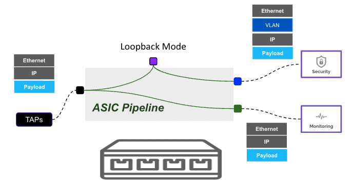
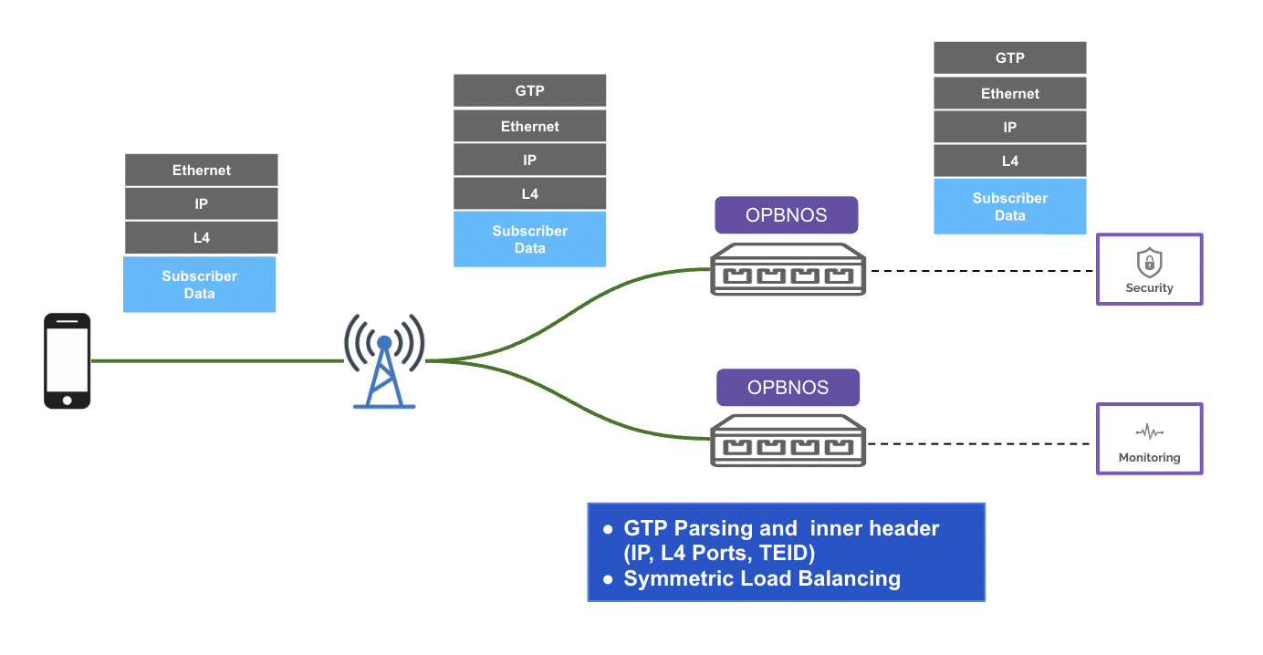
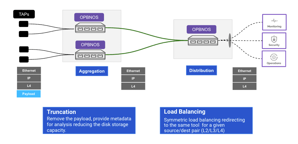
pbnoscli# save
Saving Configuration
pbnoscli# pbnoscli# show reboot-cause
Hardware - Other (Reset caused by hotswap or halt)
pbnoscli#
pbnoscli# show reboot-cause
User issued 'reboot' command [User: admin, Time: Tue 02 Aug 2022 03:01:03 AM UTC]
pbnoscli# pbnoscli# show platform syseeprom
TlvInfo Header:
Id String: TlvInfo
Version: 1
Total Length: 629
==========================================================================
TLV Name Code LEN VALUE
==========================================================================
Device Version 0x26 1 1
Product Name 0x21 64 MSN3700C
Vendor Extension 0xfd 36
Vendor Extension 0xfd 164
Vendor Extension 0xfd 36
Vendor Extension 0xfd 36
Vendor Extension 0xfd 36
Vendor Extension 0xfd 52
Manufacture Date 0x25 19 10/25/2020 20:33:38
ONIE Version 0x29 23 2019.11-5.2.0020-115200
Base MAC Address 0x24 6 1C:34:DA:24:DE:00
CRC-32 0xfe 4 0xA358E6B0
Part Number 0x22 20 MSN3700-CS2FC
Manufacturer 0x2b 8 Mellanox
Platform Name 0x28 64 x86_64-mlnx_msn3700C-r0
Serial Number 0x23 24 MT2043X14695
MAC Addresses 0x2a 2 254
pbnoscli# pbnoscli# show platform psustatus
============================================================================================================================================
PSU Model Serial Hardware Revision Voltage (V) Current (A) Power (W) Status LED
============================================================================================================================================
PSU 1 N/A N/A N/A N/A N/A N/A NOT OK red
PSU 2 MTEF-PSF-AC-C MT2042X11384 A3 12.035 7.273 88.5 OK red
pbnoscli# 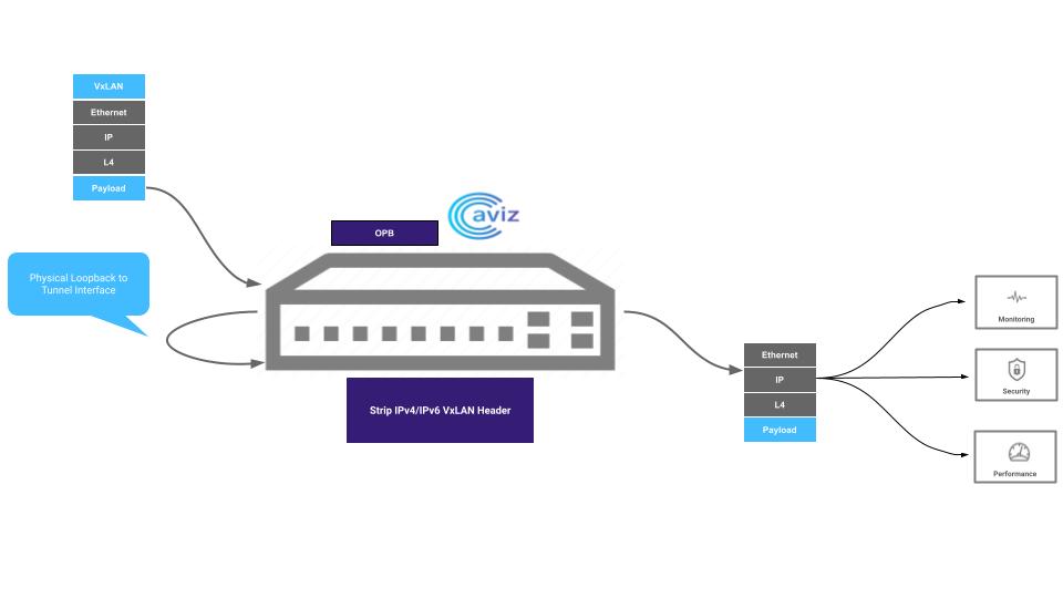
//copying running-config from remote server
pbnoscli# copy running-config scp <user>@<IP>:/<file.cfg>
//Example - copy running-config scp aviz@10.2.2.10:/rsw.cfg//copying startup-config from remote server
pbnoscli# copy startup-config scp <user>@<IP>:/<file.cfg>
//Example - copy startup-config scp aviz@10.2.2.10:/ssw.cfg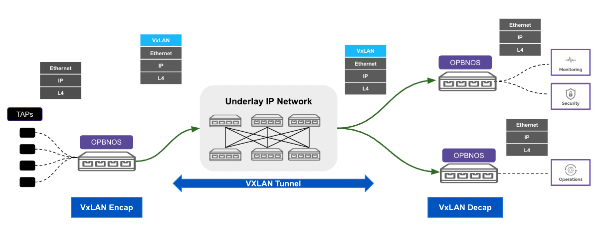
//to show running config
pbnoscli# show running-config
show running-config
configure terminal
<..>
pbnoscli#//to show startup config
pbnoscli# show startup-config
show running-config
configure terminal
port-group 1 ports Ethernet8
<..>
pbnoscli#//to copy startup config to running config
pbnoscli# copy startup-config running-config
pbnoscli#
//to copy running config to startup config
pbnoscli# copy running-config startup-config
pbnoscli#
pbnoscli# configure terminal
pbnoscli(config)# ztp force
enable run
pbnoscli(config)# ztp force
enable Enable
run Trigger ZTP process
pbnoscli(config)# ztp force enable
pbnoscli(config)# ztp force run
pbnoscli(config)# end
pbnoscli#pbnoscli(config)# ztp force enable
pbnoscli(config)# ztp force runpbnoscli(config)# ztp force enable
pbnoscli(config)# end
pbnoscli# reboot
Check if running config is saved
Do you want to reboot the device [y/n]: y
pbnoscli# show running-config
configure terminal
!
interface mgmt
ip address 10.4.4.52/24 gateway 10.4.4.1
!
ztp force enable
!
pbnoscli# pbnoscli# show platform summary
Platform: x86_64-mlnx_msn4600c-r0{
"x86_64-mlnx_msn4600c-r0": {
"FIRMWARE": {
"image": "sonicpbnos-broadcom-1.0.0.bin"
},
"CONFIGURATION": {
"config": "iscli_db.cfg"
},
"RUN_SCRIPT": {
"script": "boot_script.py"
},
"REBOOT": {
"reboot": "true"
}
}
}{
"x86_64-accton_as5812_54x-r0": {
"FIRMWARE": {
"image": "http://192.168.0.98/images/sonicpbnos-broadcom-1.0.0.bin"
},
"CONFIGURATION": {
"config": "http://192.168.0.98/images/iscli_db.cfg"
},
"RUN_SCRIPT": {
"script": "http://192.168.0.98/images/boot_script.py"
},
"REBOOT": {
"reboot": "true"
}
}
}pbnoscli# show tech-support
===============================================================================
System Uptime Information
===============================================================================
up 20 hours, 22 minutes
===============================================================================
All Services Information
===============================================================================
lldp docker
---------------------------
USER PID %CPU %MEM VSZ RSS TTY STAT START TIME COMMAND
root 1 0.0 0.3 30388 24192 pts/0 Ss+ Sep26 0:32 /usr/bin/python3 /usr/local/bin/supervisord
root 12 0.0 0.2 25616 19104 pts/0 S Sep26 0:05 python3 /usr/bin/supervisor-proc-exit-listener --container-name lldp
root 15 0.0 0.0 223808 5616 pts/0 Sl Sep26 0:00 /usr/sbin/rsyslogd -n -iNONE
<...>
s},
"default_brkout_mode": "1x100G[50G,40G,25G,10G,1G]",
"Current Breakout Mode": "1x100G[50G,40G,25G,10G,1G]",
"child ports": "Ethernet124",
"child port speeds": "100G"
}
}
pbnoscli#
pbnoscli# show tech-support dumppbnoscli# clear startup-config
This command requires a system reboot. Do you wish to continue [y/n]: ypbnoscli# show tech-support dump
===============================================================================
Generating Techsupport Tar in /var/dump
Lock succesfully accquired and installed signal handlers
mkdir: created directory '/var/dump'
<...>
Cleaning up working directory /var/dump/sonic_dump_opb-nos_20220926_184853
removed '/tmp/techsupport-lock/PID'
removed directory '/tmp/techsupport-lock'
/var/dump/sonic_dump_opb-nos_20220926_184853.tar.gz
pbnoscli# pbnoscli# copy file /var/dump/sonic_dump_opb-nos_20220926_184853.tar.gz scp aviz@10.2.2.10:/sonic_dump.tar.gzpbnoscli# copy file /var/dump/sonic_dump_opb-nos_20220926_184853.tar.gz scp aviz@10.2.2.10:/home/aviz/ravi/sonic_dump_opb-nos_20220926_184853.tar.gz
aviz@10.2.2.10's password:
sonic_dump_opb-nos_20220926_184853.tar.gz 100% 9827KB 109.7MB/s 00:00
pbnoscli# pbnoscli# show hardware-dumppbnoscli# show hardware-dump
===============================================================================
API Ports Dump
===============================================================================
<...>
----------------------------
ACL Bindings
----------------------------
==========================================================
| ACL ID| Direction| Logical Port| VLAN Group| RIF|
==========================================================
pbnoscli# pbnoscli# generate hardwaredump
[+] opening sdk
Sep 27 04:39:24 INFO LOG: Initializing SX log with STDOUT as output file.
sx_api_open handle:0x560a8bed4be4 , rc 0
No dump file path was entered as a parameter.
Will use the default: /tmp/sdkdump path.
sx_api_dbg_generate_dump, rc 0
Hardware debug dump file named hwdump, generated in /home/admin/hwdump.log
pbnoscli# pbnoscli# copy file /home/admin/hwdump.log scp <user>@<remote-ip>:/<dir>/hwdump.logpbnoscli# copy file /home/admin/hwdump.log scp aviz@10.2.2.10:/hwdump.log
The authenticity of host '10.2.2.10 (10.2.2.10)' can't be established.
ECDSA key fingerprint is SHA256:+S2EmXkMAA6WYu6VKodKZtsha3HpVzLCnpG95yEqqlQ.
Are you sure you want to continue connecting (yes/no/[fingerprint])? yes
Warning: Permanently added '10.2.2.10' (ECDSA) to the list of known hosts.
aviz@10.2.2.10's password:
hwdump.log 100% 5453KB 95.3MB/s 00:00
pbnoscli# 


pbnoscli# configure terminal
pbnoscli(config)# interface ethernet Ethernet4/1
pbnoscli(config-if)# trunc
truncate Truncate the packet
pbnoscli(config-if)# truncate 64pbnoscli# show interface npb Ethernet4/1
===================================
Interface : Ethernet4/1
===================================
Mode : vlan-aware
Ingress-vlan : 6
Egress-tagging : disable
Truncate : 64
pbnoscli# pbnoscli# sh running-config
configure terminal
!
interface ethernet Ethernet4/1
truncate 64
!
interface mgmt
ip address 10.4.4.53/23 gateway 10.4.4.1
!
pbnoscli# pbnoscli# show snmp-location
===================================================
Location
===================================================
Location-1
pbnoscli#
pbnoscli# configure terminal
pbnoscli(config)# snmp-server
community Community string authentication
contact Configure SNMP contact
location Configure SNMP location
trap Trap configuration
user SNMP user
pbnoscli(config)# snmp-server location
<loc_str>
pbnoscli(config)# snmp-server location Location-1
pbnoscli(config)#
pbnoscli(config)# no snmp-server location
pbnoscli(config)# pbnoscli# show running-config
configure terminal
!
interface mgmt
ip address 10.4.4.52/24 gateway 10.4.4.1
!
snmp-server location Location-1
!
pbnoscli#