Loading...
Loading...
Loading...
Loading...
Loading...
Loading...
Loading...
Loading...
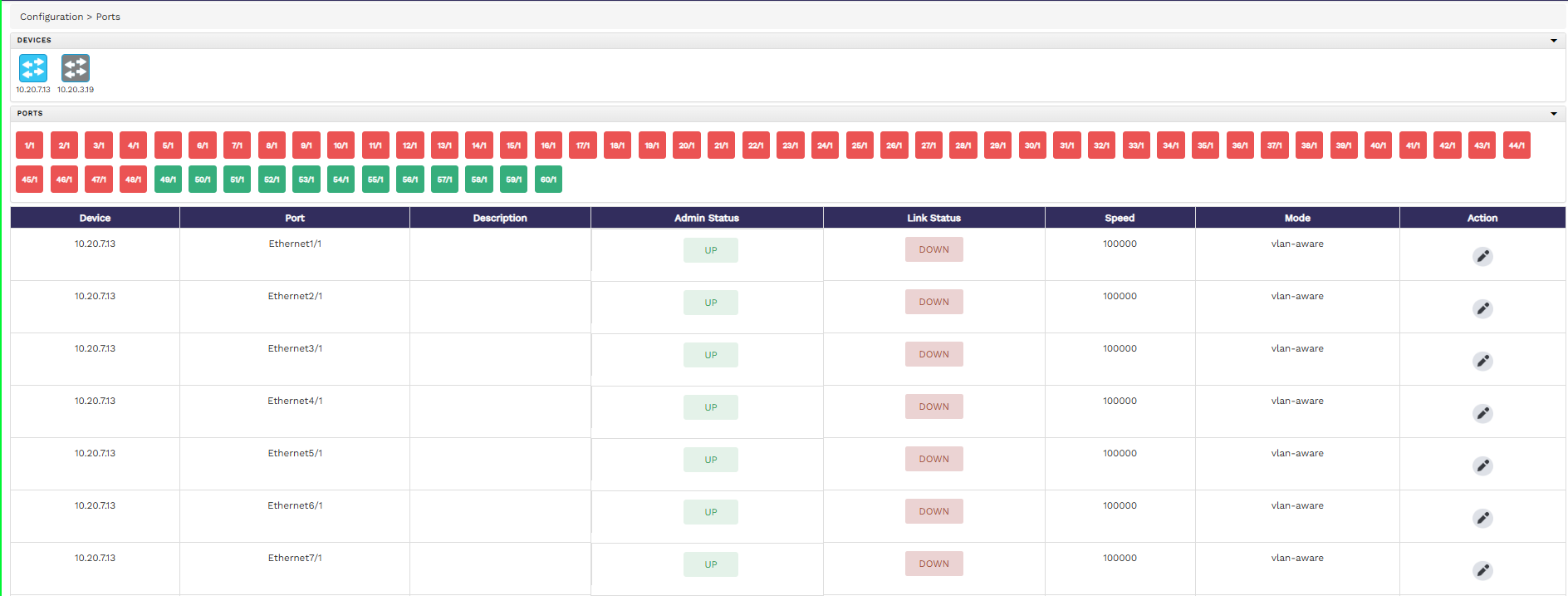
To configure the ports of the connected devices from the FlowVision GUI, click Configuration > Ports.
The Ports page shows the connected devices, the ports of each of those connected devices, and a table displaying the details of the ports, such as, the admin status, link status, speed, ingress VLAN, egress tagging, truncation, mode, and the tranceiver details. Note that, the ports that have their link status as 'UP' are shown in green, whereas the ones with the link ststus as 'DOWN' are shown in red. You can hover the mouse pointer over the devices icon or ports icon for more information on that device or port.
By default, when you select a device in the Devices section, the ports table shows you the details of all the ports of the selected device. If you want to get the details of particular ports, click the port number in the Ports section. You can also edit the properties of ports from the ports table.
The following image shows the ports page with device, ports, and port status details:
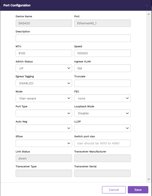
To edit the properties of a port,
Click the Edit button against the required port in the ports table. The Port Properties window displays.
Update the properties as required. The properties you can update are - Description, MTU, Speed, Admin Status, Ingress VLAN, Egress Tagging, Truncate, Mode, Fec , Port Type, Loopback Mode, Auto Neg, LLDP, sFlow and Switch Port Vlan. You can also see other non-changeable fields with more information about the selected port.
Click Save Changes
The configuration menu helps you perform the following:
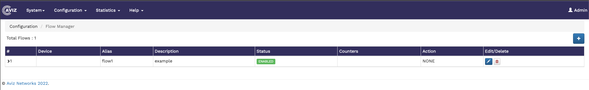
To create and configure flows from the FlowVision GUI, click Configuration > Flow Manager.
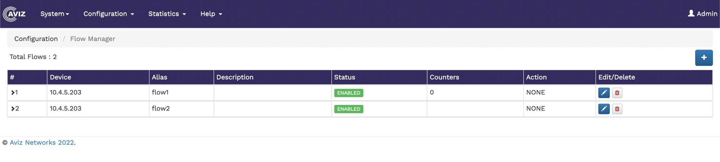
The Flow Manager page shows the number of existing flows and a table showing the flow details, such as device ID, alias, description of the flow, status, the available counters, the action performed, and an option to edit and delete flows.
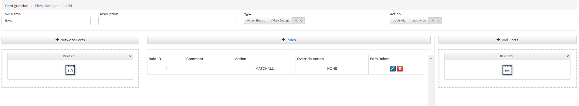
The following image shows the Flow Manager page:
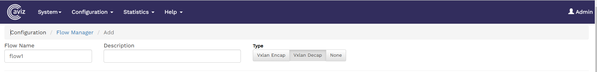
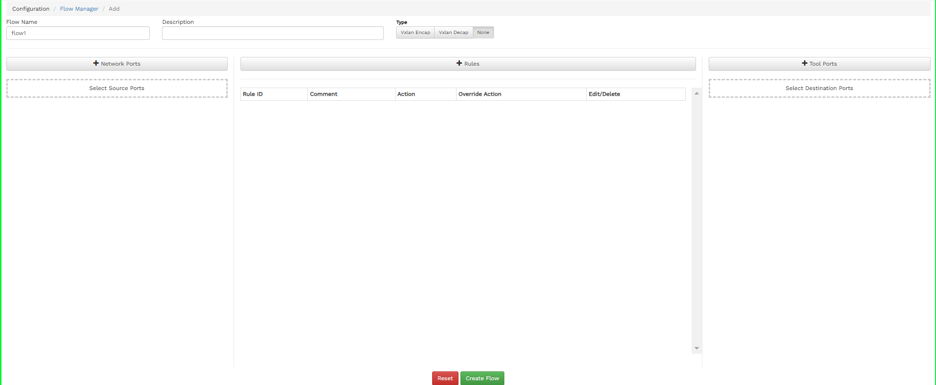
To create a new flow, click the button on the top right corner of the Flow Manager page. The Add Flow page displays.
Specify the Flow Name, Description for the Flow, and select the Action.
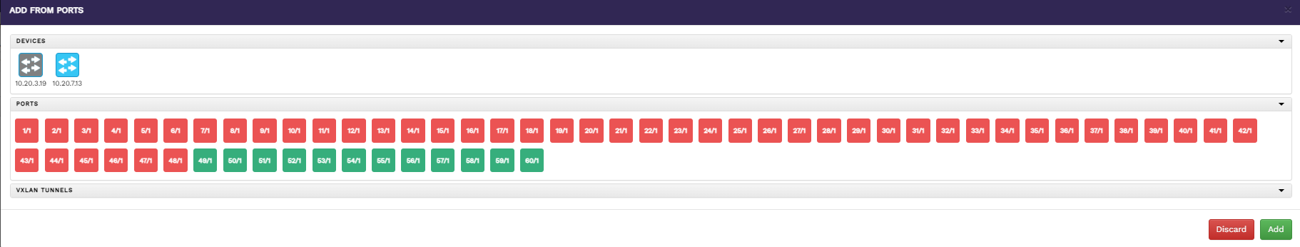
To add source ports
Click the Network Ports button on the Add Flow page. The Add From Ports window will appear as below
Select a device to list all the ports available for that device.
Select the ports you need to add as source ports.
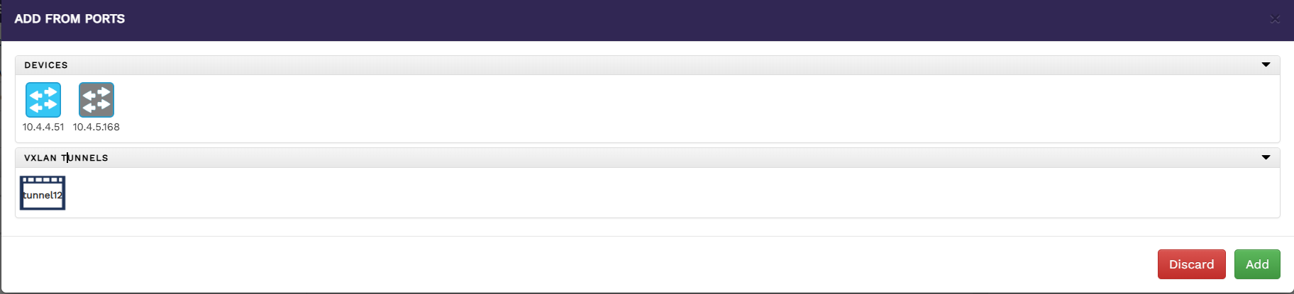
To add source ports as Vxlan Tunnel for Vxlan Decapsulation
To configure a VXLAN tunnel as a source port for VXLAN Decap:
Set the Flow Type to VXLAN Decap as shown below.
Click Network Ports button on the Add Flow page.
The Add From Ports window will appear.
Select a device to list the available Vxlan tunnel for that device.
Choose the VXLAN tunnel you want to add as a source port.
Click Add to add the tunnel to the list of source ports.
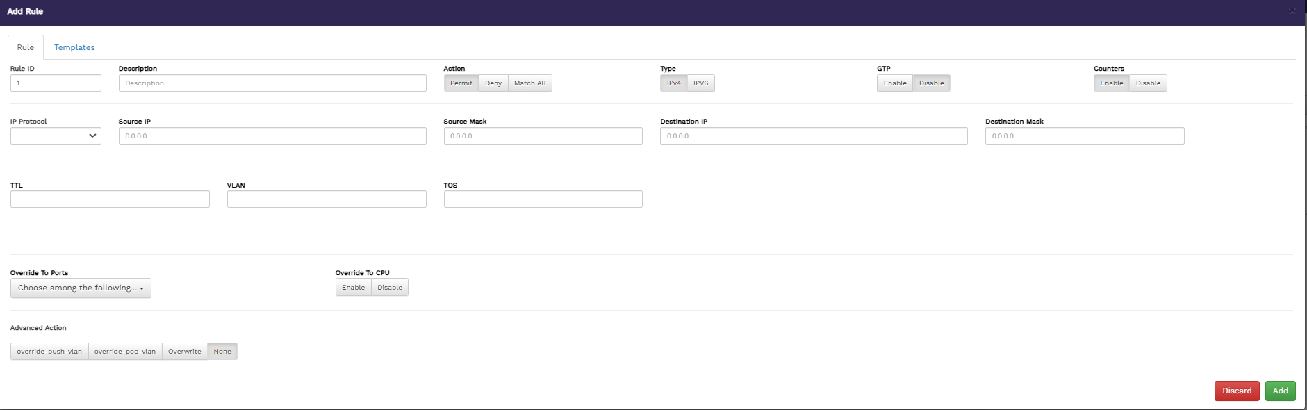
To add rules,
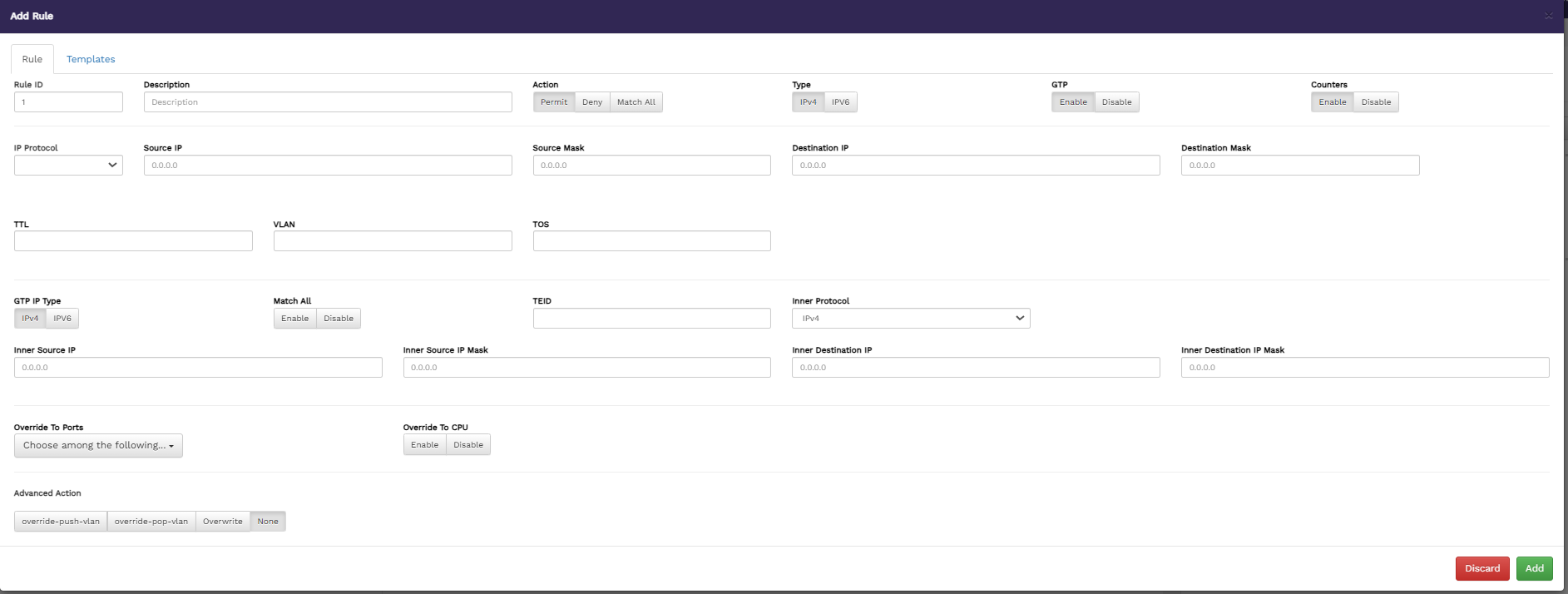
Click the Rules button on the Add Flow page. The Add Rule window displays with GTP disable.
The Add Rule window displays with GTP enable.
Specify values for the following, in the Rule tab:
Rule ID - specify a name for the new rule.
Description - enter a description of the new rule to show its purpose.
The added rules are displayed in the table below the Rules button on the Flow Manager page.
To add destination ports,
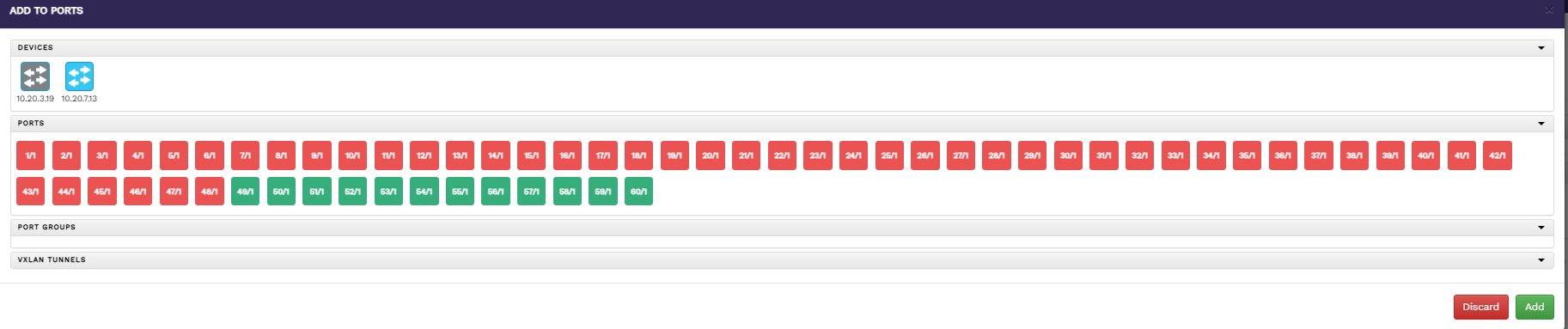
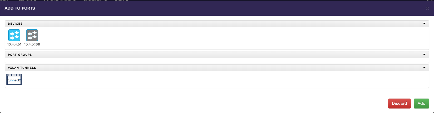
Click the Tool Ports button on the Add Flow page.
The Add To Ports window displays.
Select a device to list all the ports available for that device.
To add destination ports as Vxlan Tunnel
To configure a VXLAN tunnel as a destination port:
Set the Flow Type to VXLAN Encap.
Click Tool Ports button on the Add Flow page.
The Add To Ports window will appear.
Select a device to list the available Vxlan tunnel for that device.
Choose the VXLAN tunnel you want to add as a destination port.
Click Add to include the selected tunnel in the destination ports list.
After adding the source ports, destination ports, and rules, click Create Flow on the Add Flow page. This action creates a new flow.
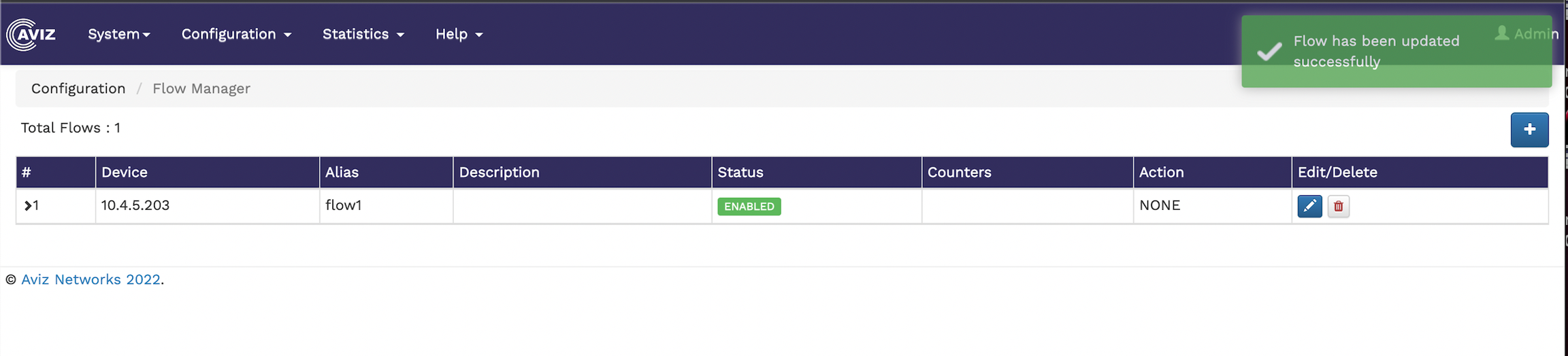
To edit an existing flow, click the icon and make your changes in the flow page. Once the modification is done, click the update button
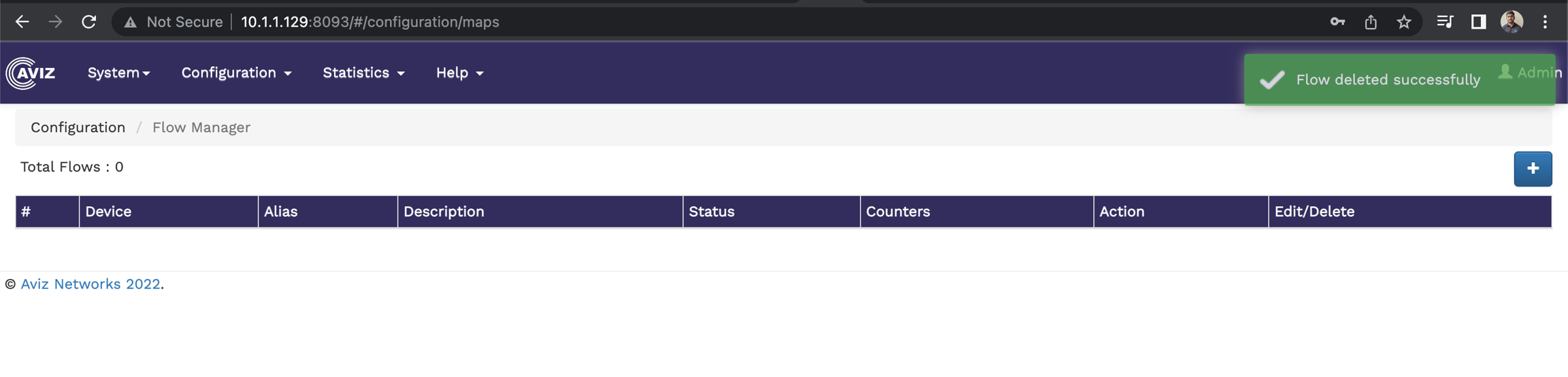
To delete the existing flow, click the icon.
Click Add to include the selected ports in the source ports list. The added ports are displayed in the field below the Network Ports button on the Add Flow page.
Action - select an action for the rule. The available options are Permit, Deny, Match All.
Type - select the IP address type. Available options are IPV4 and IPV6.
GTP - enable or disable the GTP-based filter option on a rule, when gtp enable provide GTP IP Type, Match All, TEID, Inner Protocol, Inner Source IP, Inner Source IP Mask, Inner Destination IP and Inner Destination IP Mask to match upon.
Counters - enable or disable counters.
IP Protocol - select the IP protocol for the rule. The available options are - IP, TCP, UDP,RSVP,GRE,SCTP and other. if you select others then we must provide protocol number.
Source IP - specify the source IP for the rule.
Source Mask - specify the source mask for the rule.
Destination IP - specify the destination IP for the rule.
Destination Mask - specify the destination mask for the rule.
TTL - specify the time-to-live value for the packets in the system.
VLAN - specify the VLAN details.
TOS - specify the type of service.
Override To Ports - select the override option for ports.
Advanced Action - specify the override actions. The available options are override-push-vlan, override-pop-vlan, and Overwrite. If you select override-push-vlan, you must also provide the VLAN ID, in the VLAN ID field. And if you select Overwrite ,then you must provide Destination IP or Destination mac or Destination Port.
Specify values in the Template tab. Either specify the rule options in the first tab or select the pre-defined template on the second tab. For details on the template, refer to
Click Add to add the rule.
Choose the ports you want to add as destination ports.
Click Add to include the selected ports in the destination ports list.
The added ports are displayed in the field below the Tool Ports button on the Add Flow page.

The Tunnel Configuration section in FlowVision allows users to view, create, and manage VXLAN tunnels through a graphical interface.
To view and configure Vxlan tunnel:
Navigate to Configuration > Tunnel.
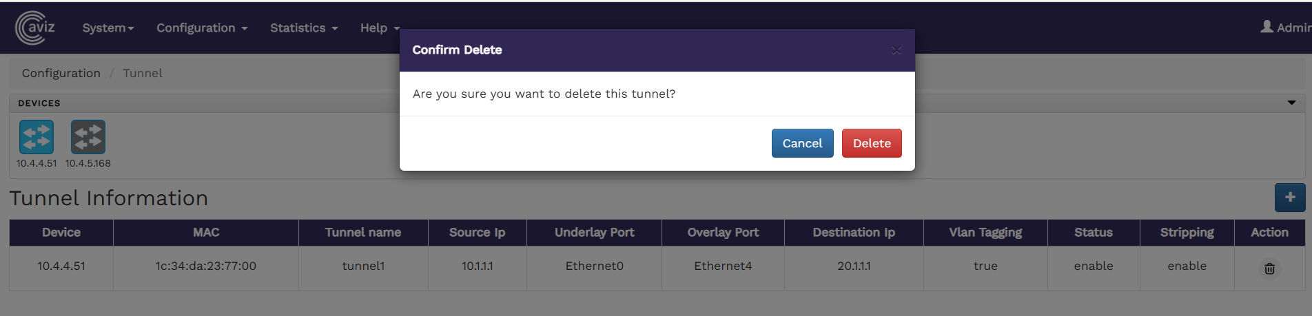
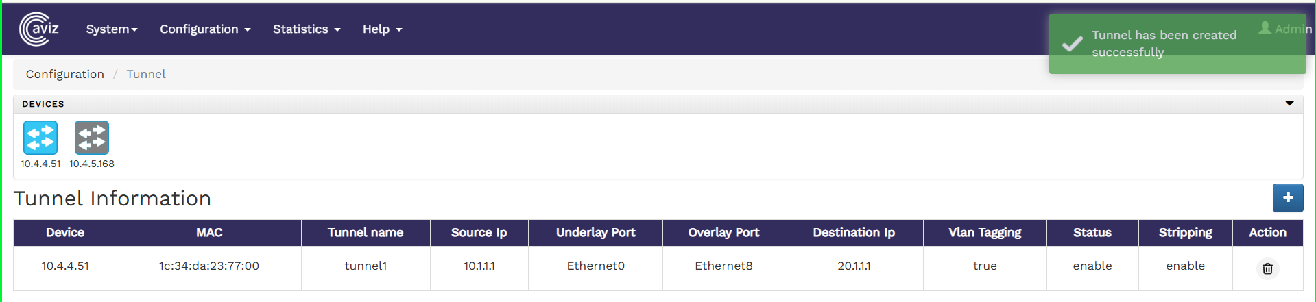
The Tunnel Information page displays:
Existing VXLAN tunnels.
A table with tunnel details, including:
Note:
Only one tunnel can be created per device.
The following image shows the Tunnel Information page:
To create a new tunnel,
Click the icon at the top right corner of the Tunnel page.
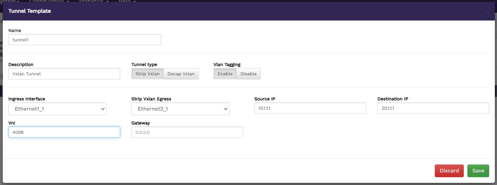
The Tunnel Template window displays.
Specify values for the following:
To delete a tunnel, click the icon next to the tunnel entry.
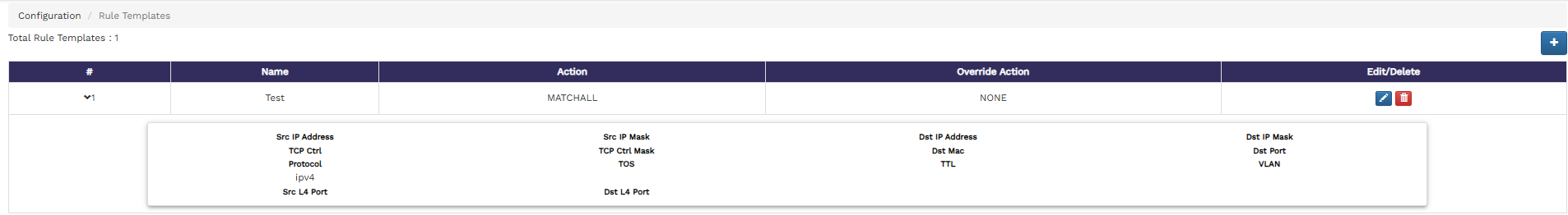
To view and configure rule templates from the FlowVision GUI, click Configuration > Rule Templates.
The Rule Templates page shows the total number of existing rule templates and a table showing the details of each of these rule templates, such as the name of the template, the action performed, the override action and also an option to edit or delete a rule template.
The following image shows the Rule Templates page:
You can group ports from a device together and create port groups. To get to the port groups page from the FlowVision GUI, click Configuration > Port Groups.
The Port Groups page shows you the connected devices and a table that shows the port groups from each device, the port group ID, the name of the ports that are part of the port group and an option to delete any existing port group.
The following image shows the Port Groups page:
To configure SNMP traps using the FlowVision GUI, navigate to Configuration > SNMP Traps.
The SNMP Traps configuration page lists connected devices and their respective configured SNMP Traps. You can select individual devices and define SNMP traps.
The following image shows the SNMP Trap page with the switches and configured SNMP Traps:
Tunnel Source IP
Tunnel Destination IP
Underlay Port
Overlay Port
VLAN Tagging
Tunnel Status
Tunnel Stripping
Delete Option
Name - specify a name for the new tunnel (must start with "tunnel")
Description - enter description of the new tunnel to show its purpose.
Tunnel Type - select the tunnel type ,two options are available i.e Encapsulation (Strip VXLAN) or Decapsulation (Decap VXLAN).
Vlan tagging- enable or disable vlan tagging for the tunnel.
Ingress interface - select the ingress tunnel port.
Strip Vxlan Egress - select the egress tunnel port.
Source IP- specify the source IP for the tunnel.
Destination IP - specify the destination IP for the tunnel.
VNI- specify the VxLAN Network Identifier.
Gateway- enter the tunnel IPv4 gateway address.
3. Click Save to apply the changes.
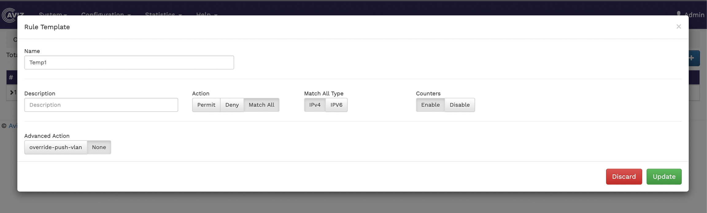
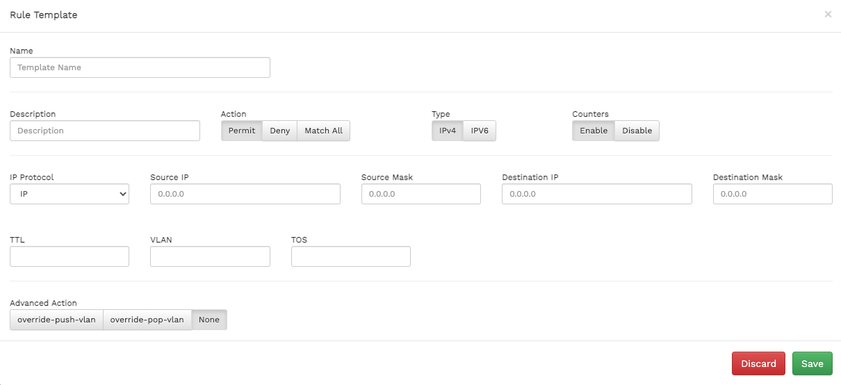
To create a new rule template,
Click the icon at the top right corner of the Rule Templates page. The Rule Template window displays.
Specify values for the following:
Name - specify a name for the new rule template.
Description - enter a description of the new rule template to show its purpose.
Action - select an action for the template. The available options are Permit, Deny, Match All.
Type - select the IP address type. Available options are IPV4 and IPV6.
Counters - enable or disable counters.
IP Protocol - select the IP protocol for the template. The available options are - IP, TCP, UDP.
Source IP - specify the source ip for the template.
Source Mask - specify the source mask for the template.
Destination IP - specify the destination IP for the template.
Destination Mask - specify the destination mask for the template.
TTL - specify the time-to-live value for the packets in the system.
VLAN - specify the VLAN details.
TOS - specify the type of service.
Advanced Action - specify the override actions. The available options are override-push-vlan, override-pop-vlan, and None.
3. Click Save to apply the changes.
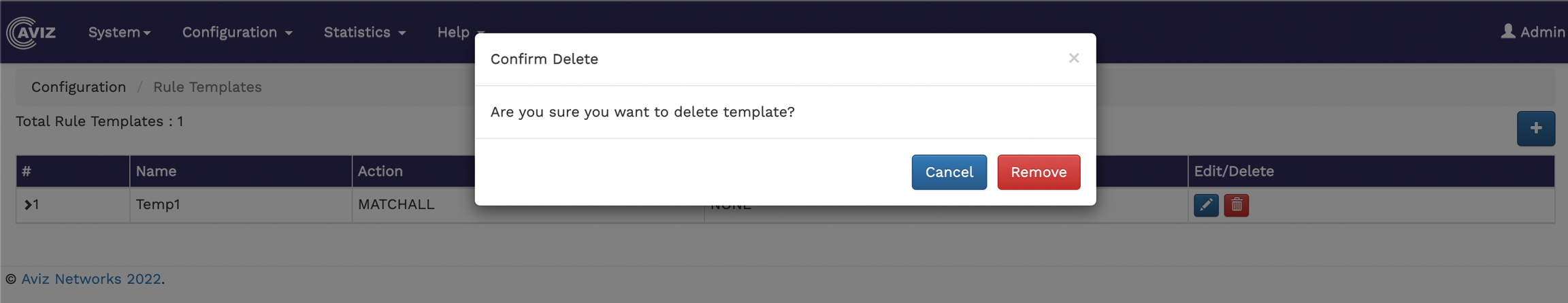
To edit an existing rule template, click the icon and make your changes in the Rule Template window.
To delete a rule template, click the icon.
To create a new port group,
Click the icon at the top right corner of the port groups page. The Port Group window displays.
Select the device where you want to create the port group.
Click the required ports to add them to the port group. The added ports are displayed in the Select ports to create Groups field.
Specify a number i.e. say 1 to 15, for the port group in the Port Group Id field.
Click Save.
Start by clicking on the button
Select the switch to configure the SNMP Trap
Configure the SNMP trap Server-ID, Version, Destination IP, Destination Port and community string
Click on
SNMP Trap is now configured
To delete the existing SNMP Trap, click the icon.
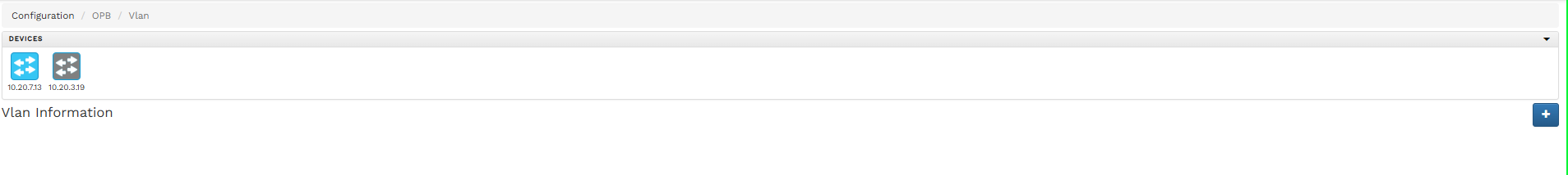
The VLAN Configuration section in FlowVision allows users to create, manage, and delete VLANs through a graphical interface.
To configure VLANs from the FlowVision GUI:
Navigate to Configuration > VLAN Configuration.
The Vlan Configuration page will display:
The total number of existing VLANs.
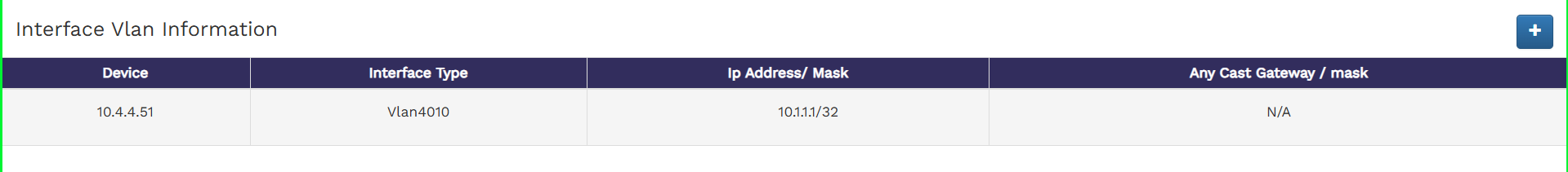
A table with VLAN details, including Device IP, Interface Type, Ip Address/ Mask ,Any Cast Gateway / mask and options to Delete VLANs.
The following image shows the VLAN Configuration page:
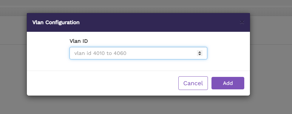
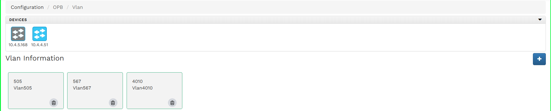
To add a new Vlan,
Click the icon at the top right corner of the Vlan Configuration page..
Enter a VLAN ID within the supported range (4010–4060).
Once created, the new VLAN will be listed under the VLAN Information section.
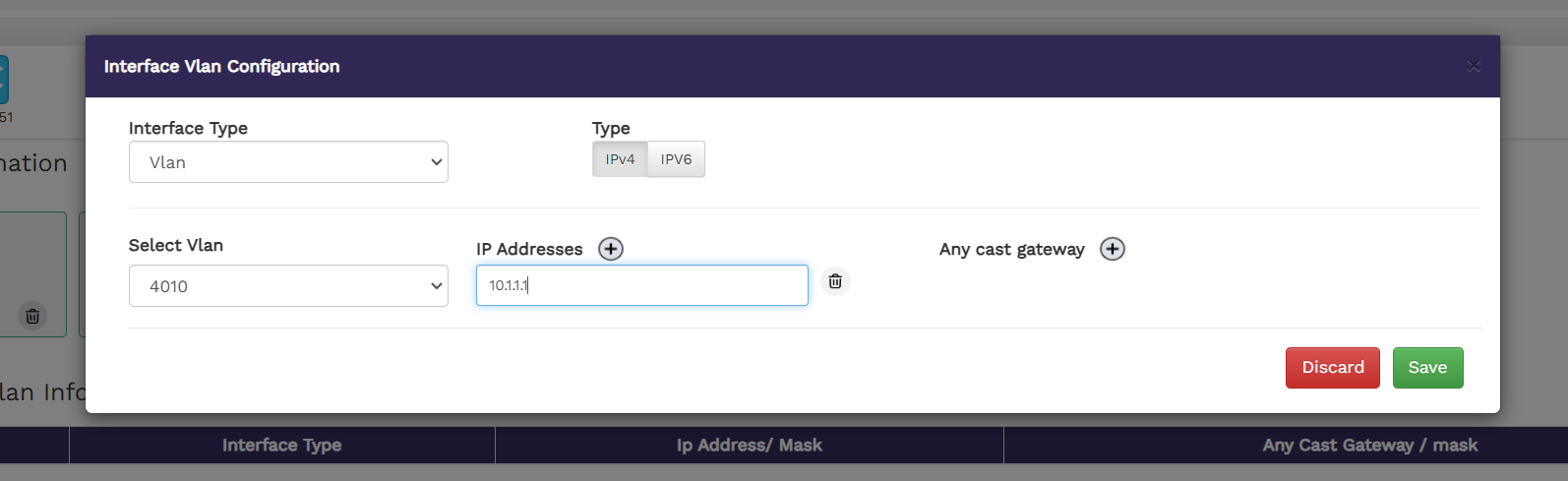
To assign an IP address to the newly created VLAN:
Click the second icon in Interface Configuration section.
Select Interface Type: VLAN from the dropdown menu.
Choose the VLAN ID, assign the IP address, and click Save.
The newly created SVI (Switched Virtual Interface) will appear in the Interface VLAN Information table as show on below
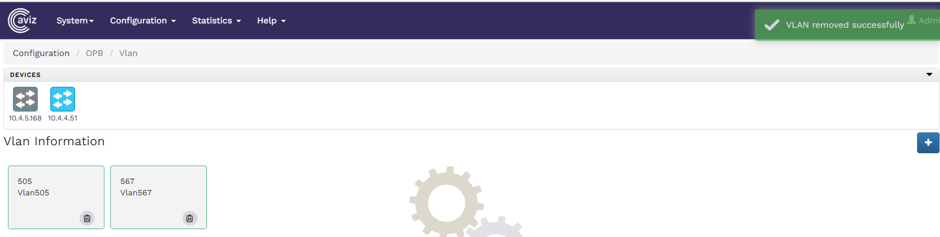
To delete the existing Vlan , click the icon.
Note: Removing an SVI requires deleting the associated VLAN. There is no option to delete only the SVI while retaining the VLAN.